Siemens 6GK1503-2CB00 Retrofit-Ready PROFIBUS OLM/G11 V4.0 for Legacy Control System Upgrades
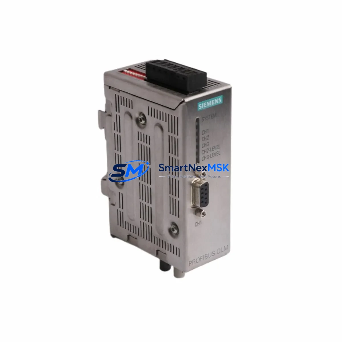
The Siemens 6GK1503-2CB00 is a PROFIBUS Optical Link Module (OLM/G11 V4.0) engineered for glass fiber optical transmission on PROFIBUS DP and FMS networks. As industrial facilities confront the challenge of sustaining aging SIMATIC S5 and early SIMATIC S7 control architectures, the 6GK1503-2CB00 has become a cornerstone retrofit component — enabling engineers to preserve existing fiber-optic ring and line topologies while migrating to modern control platforms without full network redesign. With verified compatibility across the SIMATIC S7-300 and S7-400 families, this module is the preferred replacement for discontinued OLM/G11 V1.x, V2.x, and V3.x variants in legacy control cabinets worldwide.
This module supports transmission rates from 9.6 kbit/s up to 12 Mbit/s and is fully compatible with the PROFIBUS DP protocol, making it a direct drop-in replacement for earlier OLM generations. When planning a retrofit, engineers must verify the fiber type (glass multimode 62.5/125 µm), connector style (BFOC/2.5), and segment length against the existing cable plant. The 6GK1503-2CB00 operates on a 24 VDC supply (18–32 V range) and draws approximately 200 mA, so power budget confirmation within the existing control cabinet is essential before installation — particularly in cabinets where a SITOP PSU300S or equivalent 24 VDC power supply also feeds a CP 342-5 communications processor and one or more IM 153-2 interface modules in an ET 200M remote I/O rack.
In retrofit scenarios involving SIMATIC S7-300 or S7-400 PLCs, the 6GK1503-2CB00 is typically installed alongside a CP 342-5 or CP 443-5 Extended communications processor to maintain PROFIBUS DP master functionality. Engineers migrating from older OLM/G11 V1.x or V2.x variants should note that the V4.0 firmware introduces enhanced diagnostic capabilities accessible via the STEP 7 hardware configuration tool, which may require a project update in SIMATIC Manager before the module is recognized correctly on the bus. No changes to the PLC program or PROFIBUS DP address map are required for a like-for-like replacement.
Terminal wiring on the 6GK1503-2CB00 uses a standard 9-pin Sub-D connector for the electrical PROFIBUS port and BFOC bayonet connectors for the optical ports. During replacement, technicians should label all existing fiber connections before disconnection and verify optical power levels with a fiber optic power meter to ensure the new module’s receiver sensitivity is within range (typically –3 dBm to –23 dBm at 820 nm). Bus termination resistors on the electrical segment must remain active at both ends of the copper stub, even when the primary transmission path is optical.
For control systems using a SIMATIC ET 200M distributed I/O rack populated with SM 321 digital input modules, SM 322 digital output modules, and SM 331 analog input modules, the 6GK1503-2CB00 enables the optical ring to be maintained while individual IM 153-2 interface modules are replaced or expanded. This is particularly relevant in upgrade projects where additional I/O capacity is required without disrupting the existing PROFIBUS address map. Module addresses must be confirmed in the STEP 7 hardware configuration and downloaded to the CPU — typically a CPU 315-2 DP or CPU 416-2 DP — before the new OLM is brought online.
In multi-segment PROFIBUS networks, the 6GK1503-2CB00 acts as a repeater between optical and electrical segments, allowing legacy field devices such as SIMATIC HMI OP7, OP17, or TP 270 operator panels to remain on the bus during a phased migration. This approach minimizes downtime by keeping the HMI screens and control logic active while the backbone infrastructure is upgraded. Where the installation includes a SIMATIC Panel PC or TP 1200 Comfort HMI connected via MPI or PROFIBUS, the HMI project should be backed up before any network changes are made, as address conflicts can cause the HMI to lose communication with the CPU during the transition.
When the retrofit involves a protocol migration — for example, transitioning from PROFIBUS DP to PROFINET IO — the 6GK1503-2CB00 can serve as a bridging component during the transition period, maintaining the legacy PROFIBUS segment while a SCALANCE X208 managed switch or an IE/PB Link PN IO gateway is introduced to connect new PROFINET devices. This hybrid architecture allows the existing CP 342-5 and distributed ET 200S stations to remain operational while new SIMATIC S7-1500 controllers are commissioned in parallel, protecting the original program logic and reducing migration risk.
All units supplied by SMARTNEXMSK are functionally tested prior to dispatch and covered by a 12-month warranty against manufacturing defects. Stock is maintained for immediate dispatch, supporting urgent breakdown replacement and planned maintenance shutdowns alike.
Upgrade Compatibility Table
| Parameter | 6GK1503-2CB00 (OLM/G11 V4.0) | Retrofit Notes |
|---|---|---|
| PROFIBUS Protocol | PROFIBUS DP / FMS | Compatible with all DP master/slave devices |
| Transmission Rate | 9.6 kbit/s – 12 Mbit/s | Auto-detection; match existing network baud rate |
| Optical Port | 2 × BFOC/2.5 (glass fiber) | Verify fiber type: 62.5/125 µm multimode |
| Electrical Port | 1 × Sub-D 9-pin (RS-485) | Maintain bus termination at segment ends |
| Supply Voltage | 24 VDC (18–32 V) | Confirm cabinet PSU headroom before installation |
| Current Consumption | ≈ 200 mA | Check alongside CP 342-5 / IM 153-2 draw |
| Replaces | OLM/G11 V1.x, V2.x, V3.x | Update STEP 7 HW config; re-download to CPU |
| Installation | DIN rail, 35 mm | Same footprint as prior OLM/G11 versions |
| Communication Compatibility | SIMATIC S5, S7-300, S7-400 | No program changes required for like-for-like swap |
| Commissioning Tool | SIMATIC NET OLM Config Tool / STEP 7 | Verify optical power margins and error counters |
| Pre-Shipment Test | Power-up, optical port, PROFIBUS DP comms | Tested by SMARTNEXMSK before dispatch |
| Warranty | 12 Months | From date of shipment; manufacturing defects covered |
Retrofit Planning for Existing Automation Systems
A successful retrofit begins with a complete audit of the existing PROFIBUS network topology. Before replacing the 6GK1503-2CB00, engineers should export the current STEP 7 project and document all DP slave addresses, I/O assignments, and diagnostic addresses to ensure the replacement module is configured identically. In a typical SIMATIC S7-300 installation, the OLM sits in the optical ring connecting multiple ET 200M remote I/O racks, each populated with SM 321 digital input, SM 322 digital output, and SM 331 analog input modules — all of which must remain addressable after the swap.
In control cabinets where a SITOP PSU300S 24 VDC power supply feeds both the OLM and the CP 342-5 communications processor, the total current draw must be recalculated to confirm the PSU can support the replacement module without derating. Where the cabinet also houses a TP 1200 Comfort HMI or SIMATIC Panel PC connected via MPI or PROFIBUS, the HMI project should be backed up before any network changes are made to prevent address conflicts during the transition window.
For systems using a PROFIBUS PA segment connected via a DP/PA coupler, the 6GK1503-2CB00 replacement does not affect the PA segment directly, but engineers should verify that the DP/PA coupler’s address and associated field instruments remain visible in the STEP 7 hardware configuration after the OLM swap. A controlled power-down sequence for the DP/PA segment and its field devices avoids spurious process alarms during the replacement window.
Where the existing installation uses a SIMATIC S7-400 with a CPU 416-2 DP and redundant CP 443-5 Extended modules, the 6GK1503-2CB00 can be replaced in a live ring topology by temporarily switching the ring to line mode using the OLM’s configuration port, performing the swap, and then re-enabling ring mode — a procedure that typically requires less than five minutes of partial network interruption rather than a full system shutdown. For systems with ET 200S distributed I/O stations or SIMATIC drives connected on the same PROFIBUS segment, this approach preserves process continuity for all devices not directly connected to the replaced OLM’s electrical port.
In upgrade projects that introduce a SCALANCE X208 managed switch or an IE/PB Link PN IO gateway to bridge legacy PROFIBUS slaves into a new PROFINET IO domain, the 6GK1503-2CB00 continues to serve the existing PROFIBUS segment during the transition, allowing a phased cutover that protects production continuity. A SIMATIC programming cable (PC Adapter USB or CP 5711) is required to access the OLM’s configuration port and to download updated hardware configurations to the CPU during commissioning.
Downtime Control During System Migration
Minimizing downtime during an OLM replacement requires careful pre-staging and a clear rollback plan. Before the maintenance window opens, the replacement 6GK1503-2CB00 should be pre-configured using the SIMATIC NET OLM configuration tool on a laptop, with the baud rate, optical port mode, and watchdog settings matched to the existing module’s parameters. A copy of the STEP 7 project should be loaded on the programming device and a SIMATIC Memory Card with the current CPU program should be prepared as a backup.
During the swap, the CPU should be placed in STOP mode and the PROFIBUS ring opened at the OLM’s optical ports before the module is removed from the DIN rail. The replacement module should be mounted, fiber connections re-attached in the same port order (P1 RX/TX, P2 RX/TX), and the 24 VDC supply reconnected. After power-up, the OLM’s LED status indicators should show a stable green ring status before the CPU is returned to RUN mode. If the ring status LED indicates an open ring, fiber connections should be checked for correct port assignment before proceeding.
In cases where the original program logic includes time-critical sequences — such as conveyor interlocks or press safety circuits — the CPU’s retentive data areas should be verified after restart to confirm that retain variables and data block values have been preserved. The STEP 7 diagnostic buffer should be reviewed for any new fault entries, and a full I/O force table check should be performed before handing the system back to production. Total planned downtime for a like-for-like 6GK1503-2CB00 replacement in a well-prepared environment is typically 15–30 minutes, with a clear rollback path available if the ring status cannot be restored within the maintenance window.
Retrofit Support FAQ
Q1: Is the 6GK1503-2CB00 a direct drop-in replacement for earlier OLM/G11 versions?
Yes. The V4.0 module is mechanically and electrically compatible with OLM/G11 V1.x, V2.x, and V3.x. The BFOC fiber connectors and Sub-D electrical port are identical. After installation, the STEP 7 hardware configuration should be updated to reflect the V4.0 firmware version and re-downloaded to the CPU to enable enhanced diagnostic features. No changes to the PLC program or PROFIBUS DP address map are required for a like-for-like replacement.
Q2: What wiring and interface checks are required before installation?
Verify that the 24 VDC supply is within the 18–32 V operating range under load. Confirm that bus termination resistors are active at both ends of the electrical PROFIBUS stub. Check that the BFOC fiber connectors are clean and that optical power levels at the receiver ports are within the module’s specified sensitivity range. Label all fiber connections before disconnection to avoid port reversal during reinstallation. Confirm the backplane slot and module address in the STEP 7 hardware configuration match the replacement unit before downloading.
Q3: Can the module support a phased migration from PROFIBUS DP to PROFINET IO?
Yes. The 6GK1503-2CB00 can maintain the existing PROFIBUS DP segment while a PROFINET IO infrastructure is built in parallel. An IE/PB Link PN IO gateway can be introduced to bridge legacy PROFIBUS slaves — such as ET 200M racks or SIMATIC drives — into the new PROFINET domain without removing the OLM from service. This allows a phased cutover that preserves production continuity and reduces the risk associated with a full-system migration.
Q4: What does the 12-month warranty cover, and how are units tested before shipment?
All 6GK1503-2CB00 units supplied by SMARTNEXMSK are functionally tested prior to dispatch, including power-up verification, optical port continuity, and PROFIBUS DP communication checks. The 12-month warranty covers manufacturing defects and functional failures under normal operating conditions from the date of shipment. Units are packaged in anti-static protective packaging with original or equivalent documentation. For warranty claims or technical support, contact sales@smartnexmsk.com with the order reference and a description of the fault.
© 2026 SMARTNEXMSK. All rights reserved.
Original Source: https://smartnexmsk.com
Contact: sales@smartnexmsk.com | +86 18259474341


