Siemens 6GK7343-1CX10-0XE0 Retrofit-Ready Ethernet Module for S7-300 Control Systems
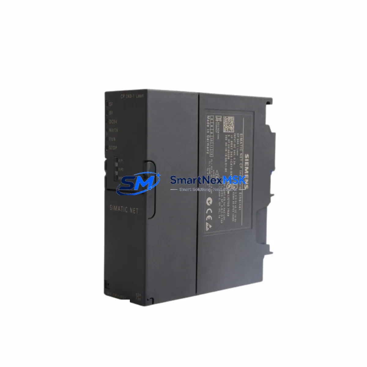
The Siemens 6GK7343-1CX10-0XE0, commonly designated as the CP 343-1, is an Ethernet communications processor engineered for the SIMATIC S7-300 programmable logic controller platform. As legacy S7-300 installations continue to operate across manufacturing, utilities, and process industries, the demand for verified retrofit-ready replacements for this module has grown significantly. Whether you are managing a planned upgrade, responding to an end-of-life parts shortage, or recovering from an unplanned failure, the 6GK7343-1CX10-0XE0 provides a direct, compatible path to restoring or modernising your Ethernet communication layer without requiring a full controller replacement.
This module supports Industrial Ethernet connectivity for the S7-300 rack, enabling TCP/IP, ISO-on-TCP, and UDP communication protocols. It integrates directly into the S7-300 backplane via the standard module bus interface, occupying a single slot in the central rack or expansion rack. The CP 343-1 allows the S7-300 CPU — such as the CPU 315-2 DP, CPU 317-2 DP, or CPU 319-3 PN/DP — to communicate with SCADA systems, HMI panels, engineering workstations, and peer PLCs over standard Ethernet infrastructure. Its compatibility with STEP 7 V5.x and TIA Portal makes it suitable for both legacy programming environments and modernised engineering workflows.
Upgrade Compatibility Table
| Parameter | Details |
|---|---|
| Replaced / Compatible SKU | 6GK7343-1CX10-0XE0 (CP 343-1); also compatible with 6GK7343-1EX30-0XE0 (CP 343-1 Advanced) migration paths |
| Target Controller Platform | SIMATIC S7-300 (CPU 312 through CPU 319 series) |
| Rack / Backplane Interface | S7-300 standard module bus; single-slot installation in CR3 or ER1/ER2 expansion racks |
| Communication Protocols | TCP/IP, ISO-on-TCP, UDP, S7 communication, FETCH/WRITE |
| Network Interface | RJ45 10/100 Mbit/s Industrial Ethernet |
| Power Supply Requirement | Supplied via S7-300 backplane bus (no external 24 VDC required) |
| Programming Environment | STEP 7 V5.5 or higher; TIA Portal V13 SP1 or higher (with HSP) |
| Installation Requirement | Module address assignment via STEP 7 hardware configuration; no DIP switch setting required |
| Commissioning Note | IP address assignment via STEP 7 or Primary Setup Tool (PST); verify existing connection blocks (FB/FC) in CPU program |
| Warranty | 12-Month Warranty — tested and verified prior to shipment |
Retrofit Planning for Existing Automation Systems
Replacing the 6GK7343-1CX10-0XE0 in an operational S7-300 system requires a structured approach to avoid configuration drift and communication loss. Before removing the existing module, engineers should document the current hardware configuration using STEP 7’s HW Config tool, capturing the module’s slot position, configured IP address, subnet mask, and all active connection resources. The CPU’s memory card — typically a Siemens MMC (Micro Memory Card) — should be backed up to preserve the loaded program and system data blocks.
In a typical S7-300 control cabinet, the CP 343-1 shares the rack with the CPU module, a PS 307 power supply module (such as the 6ES7307-1EA01-0AA0 or 6ES7307-1KA02-0AA0), and a combination of digital and analog I/O modules such as the SM 321 digital input module, SM 322 digital output module, SM 331 analog input module, and SM 332 analog output module. The IM 360 / IM 361 interface modules may also be present if expansion racks are connected. All of these modules remain in place during a CP module swap — only the communications processor is exchanged.
Terminal wiring on the CP 343-1 is limited to the RJ45 Ethernet port; there are no field terminal connections on this module itself. However, engineers should verify that the Ethernet switch port to which the module connects supports 10/100 Mbit/s auto-negotiation and that any managed switch VLAN configuration permits S7 communication traffic. If the system uses a PROFIBUS DP network alongside Ethernet — common in S7-300 installations where the CPU 315-2 DP or CPU 317-2 DP handles field device communication — the PROFIBUS segment remains unaffected by the CP module replacement.
For systems that include a TP 177B or TP 277 HMI panel connected via Ethernet to the S7-300, the HMI project’s PLC connection settings must be verified after the CP module is replaced and its IP address is reassigned. If the IP address changes, the HMI connection configuration in WinCC flexible or TIA Portal must be updated and the HMI project reloaded to the panel. Similarly, any SCADA or DCS integration using OPC DA or OPC UA over Ethernet should be tested after commissioning to confirm tag communication is restored.
Where the existing installation uses a CP 343-1 Lean (6GK7343-1CX00-0XE0) and the replacement path leads to the 6GK7343-1CX10-0XE0, engineers should note that the CX10 variant supports a greater number of simultaneous connections and additional protocol options. The STEP 7 hardware configuration must be updated to reflect the new order number, and the connection table within the NetPro tool should be reviewed to ensure all configured connections are within the new module’s capacity.
Downtime Control During System Migration
Minimising production downtime during a CP module replacement begins with pre-staging the replacement 6GK7343-1CX10-0XE0 with the correct IP address, subnet mask, and default gateway before the maintenance window opens. Using Siemens’ Primary Setup Tool (PST) or STEP 7’s accessible node function, the replacement module can be pre-configured on a bench setup and verified for network reachability before installation in the live rack.
During the replacement window, the CPU should be placed in STOP mode before the module is removed. The S7-300 backplane bus does not support hot-swapping of CP modules without a CPU stop. Once the replacement module is seated and the rack is powered, the CPU program — stored on the MMC — will reload automatically. The STEP 7 hardware configuration should then be downloaded to the CPU to register the new module’s parameters. Total replacement time for a prepared engineer is typically 15 to 30 minutes, excluding network verification.
To protect the original program logic, the CPU program should never be deleted from the MMC during the module swap. If the MMC is removed for backup purposes, it must be reinserted before the CPU is powered on. After the CP module is online, engineers should verify all configured S7 connections, FETCH/WRITE links, and TCP socket connections are re-established by checking the module’s diagnostic buffer in STEP 7 or TIA Portal. Any persistent connection faults should be investigated at the network switch level before assuming a module fault.
Retrofit Support FAQ
Q1: Is the 6GK7343-1CX10-0XE0 a direct drop-in replacement for the CP 343-1 Lean (6GK7343-1CX00-0XE0)?
A: Physically and electrically, yes — both modules occupy the same S7-300 slot and connect via the same backplane bus. However, the STEP 7 hardware configuration must be updated to reflect the new order number (6GK7343-1CX10-0XE0), as the two variants have different connection capacities and feature sets. After updating the HW Config and downloading to the CPU, all existing connection blocks in the user program remain valid.
Q2: What pre-shipment testing is performed on this module?
A: Each 6GK7343-1CX10-0XE0 unit is powered on and tested for Ethernet port functionality, backplane bus communication, and firmware integrity before dispatch. Units are supplied with a 12-month warranty covering manufacturing defects and verified operational performance. A test report is available upon request for critical infrastructure applications.
Q3: Can this module be used with a CPU 317-2 DP running an existing PROFIBUS network?
A: Yes. The CP 343-1 operates independently of the CPU’s integrated PROFIBUS DP interface. Installing the 6GK7343-1CX10-0XE0 adds Ethernet communication capability without affecting the existing PROFIBUS DP master/slave configuration. Both communication paths operate simultaneously, allowing the CPU to manage field I/O via PROFIBUS while exchanging data with SCADA or HMI systems over Ethernet.
Q4: What should be verified during commissioning after installation?
A: After seating the module and downloading the updated hardware configuration, verify the following: (1) the module’s diagnostic LED shows RUN status; (2) the assigned IP address is reachable from the engineering workstation via ping; (3) all configured S7 connections in NetPro or TIA Portal show “established” status; (4) HMI panels and SCADA clients resume tag communication; (5) the CPU diagnostic buffer contains no new CP-related fault entries. If any connection remains in “connecting” state, check switch port configuration and firewall rules on the Ethernet segment.
© 2026 SMARTNEXMSK. All rights reserved.
Original Source: https://smartnexmsk.com
Contact: sales@smartnexmsk.com | +86 18259474341


