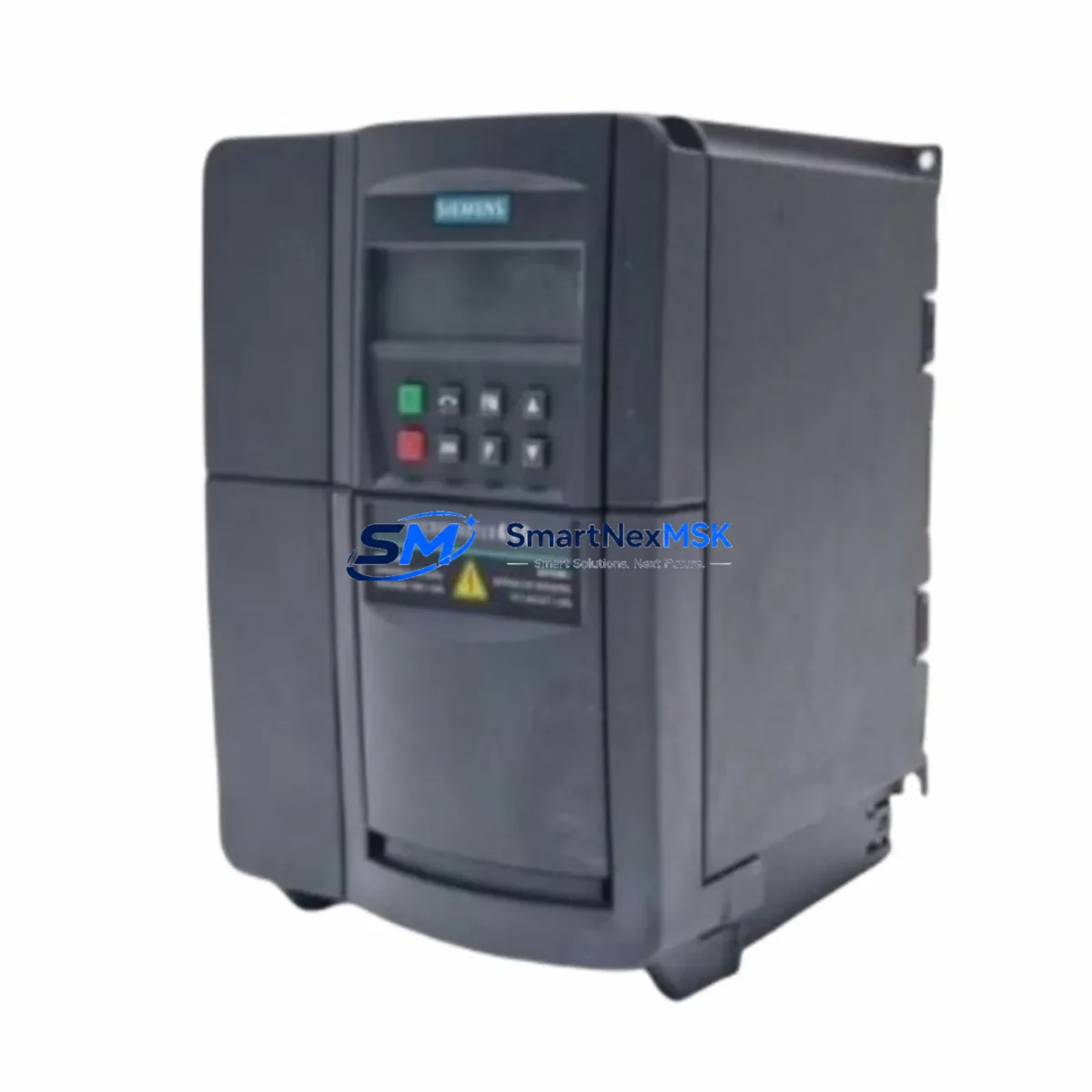
Siemens 6SE6440-2AD22-2BA1 Retrofit-Ready VFD for MM440 Control Systems
The Siemens 6SE6440-2AD22-2BA1 is a 2.2 kW, 3-phase MICROMASTER 440 series variable frequency drive engineered for demanding industrial environments. As legacy MM440 units reach end-of-service life across manufacturing plants, process lines, and utility control cabinets, this model has become one of the most sought-after retrofit and replacement components in the Siemens drive ecosystem. SMARTNEXMSK maintains verified stock of the 6SE6440-2AD22-2BA1 to support planned upgrades, emergency replacements, and phased modernization projects — with a 12-month warranty on every unit shipped.
Whether you are replacing a failed drive on a running production line, upgrading an aging control cabinet to meet current safety standards, or migrating from an obsolete MICROMASTER 420 or MICROMASTER 430 platform, the 6SE6440-2AD22-2BA1 provides a technically sound, cost-effective path forward. Its compatibility with standard PROFIBUS DP and USS protocol communication links means it integrates cleanly into existing Siemens S7-300 and S7-400 PLC architectures without requiring full program rewrites or HMI screen redesigns.
Upgrade Compatibility Table
| Parameter | Details |
|---|---|
| SKU / Part Number | 6SE6440-2AD22-2BA1 |
| Series | MICROMASTER 440 (MM440) |
| Power Rating | 2.2 kW (3-phase, 380–480 V AC input) |
| Output Current | 5.9 A continuous |
| Communication Interfaces | USS protocol (RS-485); optional PROFIBUS DP via CB15 module |
| Installation Format | Panel-mount / DIN rail compatible; standard MM440 footprint |
| Replaces / Compatible With | MM420, MM430, MM440 same-frame variants; G120C (with wiring adaptation) |
| Terminal Compatibility | Standard MM440 control terminal strip (DIN 1–DIN 6, AIN, AOUT, relay outputs) |
| Retrofit Recommendation | Direct drop-in for same-frame MM440 units; verify power supply capacity before installation |
| Commissioning Tool | STARTER software or BOP-2 operator panel; parameter set migration via P0010 / P0970 |
| Debugging Focus | Motor data re-identification (P1910), encoder feedback check, fault history reset (P0952) |
| Warranty | 12 months from shipment date — covers manufacturing defects and functional failure |
Retrofit Planning for Existing Automation Systems
A successful retrofit of the 6SE6440-2AD22-2BA1 into an existing control cabinet begins well before the physical swap. Engineers should first audit the incoming power supply capacity — the MM440 2.2 kW frame draws up to 6.8 A at full load, and undersized circuit breakers or aging transformer taps are a common source of nuisance trips after installation. Confirm that the 24 V DC auxiliary supply feeding the control terminal strip is stable, particularly if the cabinet also powers a Siemens OP 77B or TP 177B HMI panel on the same rail.
Terminal wiring on the MM440 control board follows a well-documented layout, but field engineers frequently encounter legacy cabinets where DIN 3 (forward/reverse) and DIN 4 (fault reset) have been repurposed or jumpered differently from the factory default. Before removing the old drive, photograph and document every terminal connection, including the analog input AIN+ / AIN- used for speed reference from a Siemens S7-300 analog output module such as the SM 332. If the existing system uses a PROFIBUS DP network, verify that the CB15 PROFIBUS communication board is present on the replacement unit or order it separately — the base 6SE6440-2AD22-2BA1 ships with USS/RS-485 only.
For sites running a Siemens S7-400 CPU with a CP 443-5 PROFIBUS master, the drive’s GSD file must be re-imported into STEP 7 or TIA Portal if the slave address has changed. Address conflicts on the PROFIBUS segment — especially when the old drive occupied address 3 or 5 alongside ET 200S distributed I/O nodes — are a leading cause of communication faults during first power-up. Assign the new drive address via P0918 before connecting to the live bus.
Backplane and rack considerations apply when the MM440 is installed adjacent to a Siemens S7-300 rack using a PS 307 power supply module. Ensure adequate clearance for the drive’s cooling airflow — the MM440 frame B requires a minimum 100 mm clearance above and below. If the control cabinet also houses an ET 200M I/O station or a CP 343-1 Ethernet module, verify that the drive’s switching frequency (P1800) is not inducing EMC interference on the communication cables. Shielded cable termination at the PE bar is mandatory.
Parameter migration from the old drive is straightforward if the previous unit’s parameter set was backed up to a BOP-2 operator panel or exported via STARTER. Upload the saved parameter file, then run motor data identification (P1910 = 1) to re-characterize the connected motor — this step is critical when the replacement drive is from a different production batch, even within the same MM440 series. After identification, verify ramp-up time (P1120), ramp-down time (P1121), and the PID controller setpoint source (P2253) if the drive is operating in closed-loop process control mode.
Downtime Control During System Migration
Minimizing production downtime during a drive replacement requires a structured pre-commissioning approach. Before the maintenance window opens, prepare a complete parameter backup from the existing 6SE6440-2AD22-2BA1 (or its predecessor) using the BOP-2 panel’s upload function or STARTER’s offline project. This backup preserves all application-specific settings — ramp times, PID gains, fault response configurations, and digital input assignments — so that the replacement unit can be brought to operational state within minutes rather than hours.
During the physical swap, keep the S7-300 or S7-400 CPU in STOP mode and isolate the drive’s main power contactor before disconnecting terminals. Label every wire with its terminal designation before removal. If the site uses a Siemens SIMATIC WinCC SCADA system, place the affected drive tag in manual override mode to prevent the HMI from generating spurious alarms during the changeover. For lines where even brief interruptions are critical — such as continuous process applications with a Siemens FM 355 PID controller managing temperature or pressure — coordinate the swap during a scheduled production break and have a pre-tested spare unit on the bench ready to install.
After installation, perform a no-load test first: energize the drive without connecting the motor, verify that the control terminal inputs respond correctly (use P0700 / P0701 to check digital input status), and confirm that the PROFIBUS or USS communication link is established (check r2090 for USS status word or r2051 for PROFIBUS diagnostics). Only then connect the motor and run a low-speed jog (P1058) before returning to full automatic control. This sequence protects both the motor and the downstream mechanical load from unexpected torque transients during the first powered run.
Retrofit Support FAQ
Q1: Is the 6SE6440-2AD22-2BA1 a direct replacement for an existing MM440 unit of the same power rating?
Yes. The 6SE6440-2AD22-2BA1 is a frame-B MM440 drive and is dimensionally and electrically compatible with other MM440 units of the same frame size. Terminal layout, mounting hole pattern, and control board connector positions are identical. If replacing a unit from a different MM440 sub-series (e.g., 6SE6440-2AD21-5BA1 at 1.5 kW), verify that the motor’s rated current falls within the new drive’s output range before installation.
Q2: Can this drive communicate with a Siemens S7-300 PLC over PROFIBUS DP?
The base unit supports USS protocol over RS-485. PROFIBUS DP communication requires the optional CB15 communication board, which mounts directly onto the MM440 control board. If your existing installation uses PROFIBUS DP with a CP 342-5 or CP 343-5 module on the S7-300 rack, confirm that the CB15 board is included with your order or procured separately. SMARTNEXMSK can advise on CB15 availability alongside the main drive unit.
Q3: What wiring changes are needed when retrofitting from an MM420 to this MM440 unit?
The MM420 and MM440 share a similar control terminal philosophy but differ in the number of available digital inputs and relay outputs. The MM440 provides six digital inputs (DIN 1–6) versus three on the MM420, and adds a second analog output. When migrating, map existing MM420 terminal assignments to the corresponding MM440 terminals, and review parameter P0700 (command source) and P1000 (frequency setpoint source) to ensure they match your control architecture. No changes to the main power wiring (L1/L2/L3 input, U/V/W motor output) are required if cable sizing is appropriate for the 2.2 kW rating.
Q4: What does the 12-month warranty cover, and how is it handled?
Every 6SE6440-2AD22-2BA1 unit shipped by SMARTNEXMSK carries a 12-month warranty from the date of shipment, covering manufacturing defects and functional failure under normal operating conditions. Units are tested prior to dispatch. In the event of a warranty claim, contact our technical team with the order reference and fault description; we will arrange a replacement or repair with priority handling to minimize your downtime. The warranty does not cover damage resulting from incorrect installation, overvoltage events, or operation outside the drive’s rated environmental conditions.
© 2026 SMARTNEXMSK. All rights reserved.
Original Source: https://smartnexmsk.com
Contact: sales@smartnexmsk.com | +86 18259474341


