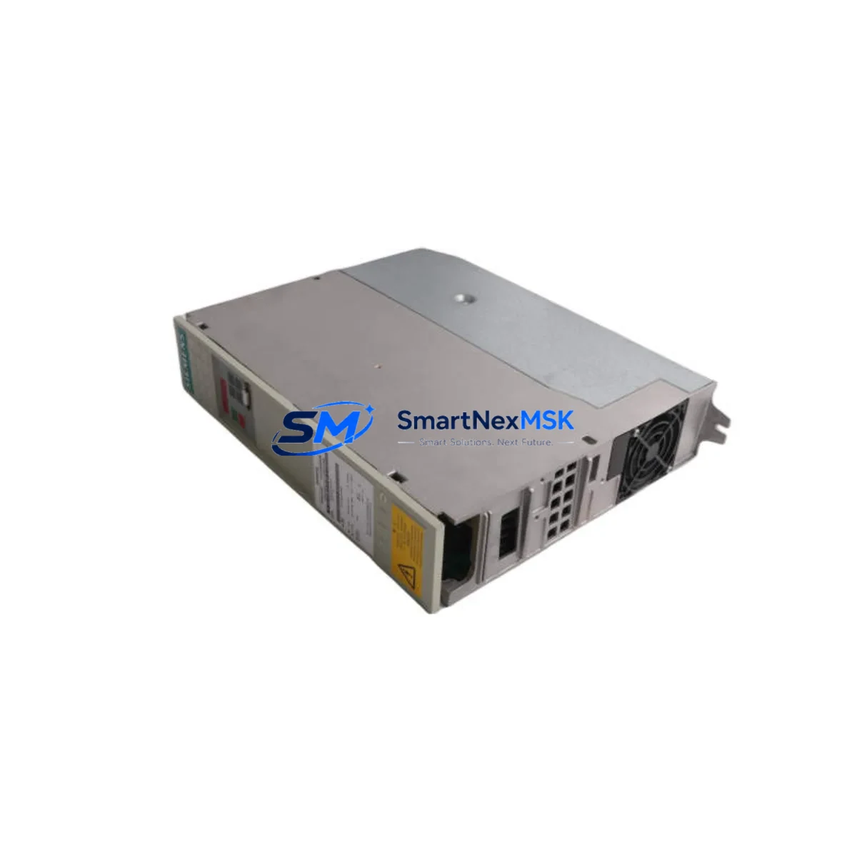
Siemens 6SE7021-0EA51-Z Retrofit-Ready AC Drive for SIMOVERT MASTERDRIVES Control Systems
The Siemens 6SE7021-0EA51-Z (options C33+F01+G91) is a 4 kW vector-control AC variable frequency drive from the SIMOVERT MASTERDRIVES MC series — one of Siemens’ most widely deployed drive platforms in industrial automation. As the original MASTERDRIVES lineup approaches end-of-life and spare parts become increasingly scarce, this unit serves as a verified retrofit-ready replacement for aging installations across manufacturing, material handling, pump control, and process automation environments.
Whether you are managing a planned upgrade cycle or responding to an unplanned drive failure, the 6SE7021-0EA51-Z provides a direct-fit solution that preserves your existing cabinet wiring, motor connections, and — in most cases — your existing STEP 7 or DriveMonitor parameter sets. The C33 option adds the CBP2 PROFIBUS-DP communication board, enabling seamless integration into SIMATIC S7-300 and S7-400 PLC networks without protocol migration. The F01 option provides the basic operator panel (BOP), and G91 adds the DC link choke for improved harmonic performance and grid compatibility.
Upgrade Compatibility Table
| Parameter | Details |
|---|---|
| SKU / Part Number | 6SE7021-0EA51-Z C33+F01+G91 |
| Series | SIMOVERT MASTERDRIVES MC (Motion Control) |
| Power Rating | 4 kW (5.5 HP), 3-phase 380–480 V AC input |
| Output Current | 10.2 A nominal |
| Communication | PROFIBUS-DP via CBP2 board (C33 option) |
| Mounting / Form Factor | Compact chassis, standard DIN rail or panel mount |
| Replaces / Compatible With | 6SE7021-0EA51, 6SE7021-0EB51, earlier -0EA51 variants |
| PLC Compatibility | SIMATIC S7-300, S7-400, S7-1500 (via PROFIBUS gateway) |
| HMI Compatibility | SIMATIC HMI TP/OP panels via PROFIBUS; DriveMonitor via RS232 |
| Commissioning Tool | DriveMonitor, STARTER, SIMATIC Manager |
| Retrofit Wiring | Terminal-compatible with standard MASTERDRIVES compact chassis |
| Warranty | 12 months from date of shipment |
| Condition | New / Surplus New / Tested Refurbished (specify at order) |
Retrofit Planning for Existing Automation Systems
Replacing a failed or end-of-life MASTERDRIVES unit requires careful pre-installation verification across several system layers. Before removing the existing drive, document the full parameter set using DriveMonitor or the STARTER commissioning tool — this preserves motor data, ramp times, torque limits, and any application-specific function blocks that may have been programmed during original commissioning.
On the hardware side, verify that the existing 6SE7 compact chassis backplane and power bus connections are compatible with the replacement unit’s terminal layout. The 6SE7021-0EA51-Z uses the standard MASTERDRIVES compact chassis terminal block arrangement, so in most cases the DC bus connections, motor output terminals (U2/V2/W2), and control terminal strip (X101/X102) will align directly with the existing cabinet wiring. If the installation includes a 6SY7010-0AA00 or similar braking resistor module, confirm that the chopper threshold and resistor rating remain within specification for the replacement drive’s firmware version.
For sites running SIMATIC S7-300 CPUs such as the CPU 315-2 DP or CPU 317-2 DP, the CBP2 PROFIBUS-DP board (included via the C33 option) allows the drive to appear on the existing DP network without any changes to the PLC hardware configuration — provided the GSD file for the 6SE70 drive family is already loaded in SIMATIC Manager. If the site uses a newer S7-1500 controller, a PROFIBUS-to-PROFINET gateway such as the IE/PB Link PN IO may be required to bridge the communication protocols.
I/O wiring should be verified against the existing terminal diagram. The 6SE7021-0EA51-Z supports analog speed reference inputs (0–10 V or 4–20 mA) on the X101 terminal strip, along with digital inputs for RUN/STOP, fault reset, and speed preset selection. If the original installation used a 6SE7090-0XX84-0KA0 technology board or a CBP (first-generation PROFIBUS board), note that the C33 option uses the CBP2 — confirm that the PLC’s DP master configuration references the correct GSD file to avoid address conflicts.
Sites that include SIMATIC HMI panels — such as the TP177B or OP177B — connected to the drive via PROFIBUS should verify that the HMI screen tags referencing drive status words, speed feedback, and fault codes remain valid after the swap. In most cases, the process data object (PDO) mapping of the MASTERDRIVES series is consistent across firmware generations, but a full HMI tag audit is recommended before returning the system to production.
If the control cabinet also houses a 6EP1 series SITOP power supply module, verify that the 24 VDC control voltage rail can support the inrush current of the replacement drive’s control electronics during power-up. Similarly, if a 6SN1 SIMODRIVE module or a 6RA70 DC drive is installed in the same cabinet on a shared DC bus, confirm that the DC link voltage balance is maintained after the replacement.
Downtime Control During System Migration
Minimizing production downtime during a MASTERDRIVES replacement begins with advance preparation. Before the maintenance window opens, upload and archive the complete parameter set from the existing drive using DriveMonitor — save the .drv file to a secure location and print a hard copy for on-site reference. Pre-configure the replacement 6SE7021-0EA51-Z offline using the same tool, loading the archived parameters and adjusting only those values that differ due to firmware version changes or option board differences.
During the physical swap, label all control wiring before disconnection and photograph the terminal strip layout. The standard MASTERDRIVES compact chassis can typically be exchanged in under 60 minutes by an experienced technician, provided all parameters are pre-loaded and the PROFIBUS node address is set correctly on the CBP2 board before installation. After power-up, perform a motor identification run if the motor data has changed, then verify speed reference tracking, fault relay outputs, and PROFIBUS communication status from the S7 CPU’s diagnostic buffer before releasing the line to production.
For critical processes where even brief interruptions are unacceptable, consider staging the replacement drive in a test cabinet with a matched motor load to validate parameter compatibility and communication behavior before the live swap. This approach — combined with pre-tested wiring adapters and a documented commissioning checklist — can reduce on-site installation time to under 30 minutes and virtually eliminate the risk of post-swap commissioning delays.
Retrofit Support FAQ
Q: Is the 6SE7021-0EA51-Z a direct drop-in replacement for the earlier 6SE7021-0EA51 without the Z suffix?
A: In most cases, yes. The Z suffix indicates factory-fitted options (C33+F01+G91 in this configuration). The base drive hardware and terminal layout are identical to the standard 6SE7021-0EA51. Verify that your existing installation does not rely on option boards not included in this configuration — such as a technology board or encoder interface — before ordering.
Q: Can I reuse my existing parameter set from the failed drive?
A: Yes, provided the parameter set was backed up using DriveMonitor or STARTER prior to the failure. If no backup exists, the motor nameplate data and application-specific settings will need to be re-entered manually. We recommend performing a motor identification run after installation to optimize current controller gains for your specific motor.
Q: What commissioning steps are required for the PROFIBUS connection?
A: Set the PROFIBUS node address on the CBP2 board using the address switches before powering up the drive. Ensure the correct GSD file for the 6SE70 drive family is installed in your SIMATIC Manager or TIA Portal project. Verify that the DP master’s slot configuration matches the drive’s telegram type (typically Telegram 1 or Telegram 5 for standard speed control). Check the CBP2 LED status indicators after power-up to confirm DP communication is active.
Q: What does the 12-month warranty cover, and how is the unit tested before shipment?
A: All units are functionally tested prior to shipment, including power-up verification, parameter upload/download, and PROFIBUS communication check where applicable. The 12-month warranty covers defects in materials and workmanship under normal operating conditions. Units showing damage from incorrect installation, overvoltage events, or environmental contamination are excluded. Contact sales@smartnexmsk.com for warranty claims or technical support.
© 2026 SMARTNEXMSK. All rights reserved.
Original Source: https://smartnexmsk.com
Contact: sales@smartnexmsk.com | +86 18259474341


