SIGMATEK 01-450-031 Retrofit-Ready CPU for DIAS Control Systems
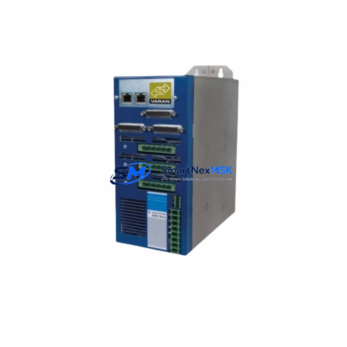
The SIGMATEK 01-450-031 is a high-performance CPU module built on the AMD LX800 processor platform with 256 MB of onboard RAM, designed for seamless integration into the SIGMATEK DIAS (Distributed Industrial Automation System) control architecture. As legacy DIAS installations age and original spare parts become increasingly difficult to source, this module serves as the definitive retrofit-ready replacement — enabling engineers to restore, upgrade, and future-proof existing control systems without redesigning the entire control cabinet.
Whether you are replacing a failed unit on a production line, upgrading an aging DIAS rack to extend its operational lifespan, or migrating from an earlier CPU revision, the 01-450-031 provides the processing headroom, communication compatibility, and backplane interface consistency required for a smooth transition. This module is stocked, tested, and shipped with a 12-month warranty from our Xiamen facility.
Upgrade Compatibility Table
| Parameter | Details |
|---|---|
| SKU / Part Number | 01-450-031 |
| Processor | AMD LX800 (500 MHz) |
| RAM | 256 MB DDR |
| Compatible Series | SIGMATEK DIAS (Distributed Industrial Automation System) |
| Backplane Interface | DIAS backplane bus — compatible with standard DIAS rack systems |
| Communication Ports | Ethernet (100 Mbit), RS-232/RS-485 serial, CANopen |
| Communication Compatibility | CANopen, Ethernet/IP, Modbus TCP — verify firmware revision before swap |
| Installation Requirement | Standard DIAS rack slot; no mechanical modification required |
| Replacement Recommendation | Direct drop-in for earlier 01-450-0xx CPU revisions; confirm firmware version with LASAL project file |
| Commissioning Focus | IP address reassignment, node ID configuration, LASAL project reload, I/O mapping verification |
| Warranty | 12 Months — covers manufacturing defects and functional failure under normal operating conditions |
Retrofit Planning for Existing Automation Systems
Retrofitting a SIGMATEK DIAS system requires a structured approach that accounts for every layer of the control architecture. Before removing the existing CPU, engineers should document the current rack configuration — noting the slot positions of all installed modules including the DIAS-I/O digital input/output modules, any DIAS-AIO analog I/O expansion cards, and the DIAS power supply module (typically a 24 VDC rail-mount unit feeding the backplane). Verifying that the power supply can sustain the current draw of the 01-450-031 under full I/O load is a critical pre-installation step.
The backplane itself — whether a 4-slot, 8-slot, or 12-slot DIAS rack — must be inspected for connector wear and proper grounding before the new CPU is seated. If the existing rack shows signs of corrosion or damaged bus connectors, replacing it with a new DIAS rack chassis at the same time as the CPU swap eliminates a common source of intermittent faults post-retrofit.
Communication architecture is another key consideration. Many legacy DIAS installations rely on CANopen as the primary fieldbus for connecting remote I/O nodes, drives, and HMI panels. The 01-450-031 supports CANopen natively, but node IDs and baud rate settings must be reconfigured to match the original network topology. If the system also uses Modbus TCP or Ethernet/IP for SCADA integration or third-party device communication, the Ethernet port configuration — including IP address, subnet mask, and gateway — must be re-entered after the CPU swap, as these settings are stored on the module itself.
For sites running SIGMATEK LASAL programming software, the existing project file (.lpr) should be backed up before any hardware change. After installing the 01-450-031, the project is reloaded via the LASAL IDE over Ethernet or the onboard USB programming interface. Engineers should verify that the firmware version on the new CPU is compatible with the LASAL project revision — mismatches between CPU firmware and project compiler version are the most common cause of startup errors during retrofit commissioning.
If the control system includes a SIGMATEK HMI panel (such as a DIAS-compatible touch panel or a third-party panel connected via serial or Ethernet), the HMI communication driver and tag database should be validated after the CPU is online. Screen navigation, alarm acknowledgment, and data logging functions should all be tested against the original HMI project before returning the line to production.
For systems that incorporate DIAS motion control modules or servo drive interfaces, axis parameters — including encoder resolution, velocity limits, and homing sequences — must be re-verified after the CPU replacement, as these are typically stored in the CPU’s non-volatile memory or in the LASAL project configuration. Similarly, any DIAS communication gateway modules bridging PROFIBUS, DeviceNet, or EtherCAT segments should be checked for correct master/slave addressing after the new CPU comes online.
Downtime Control During System Migration
Minimizing unplanned downtime during a CPU retrofit is the primary operational concern for most industrial sites. The recommended approach is to pre-configure the replacement 01-450-031 module off-line before the scheduled maintenance window. Using a bench test setup — a spare DIAS rack, a laptop running LASAL, and a copy of the production project file — the new CPU can be loaded with the correct firmware, assigned the correct IP address and CANopen node parameters, and verified for basic communication before it ever enters the control cabinet.
During the actual swap, the sequence should follow a defined lockout/tagout procedure: isolate the control cabinet power, remove the failed or legacy CPU from its rack slot, seat the pre-configured 01-450-031, restore power, and confirm that the LASAL runtime loads and all I/O modules report correctly on the backplane bus. A well-prepared retrofit of this type can be completed in under two hours, keeping production interruption to a minimum.
To protect the original program logic, always maintain at least two independent backups of the LASAL project file — one on the engineering laptop and one on a network share or USB drive stored separately from the control cabinet. If the system uses any retain variables (non-volatile data such as batch counters, recipe parameters, or production totals), these should be exported from the old CPU before shutdown if the hardware still allows it, and re-imported after the new CPU is commissioned. This preserves operational continuity and avoids the need to manually re-enter production data after the retrofit.
Field control continuity during the migration window can be maintained by placing any downstream drives, valves, or actuators in manual/local mode at the field device level, ensuring that the process remains in a safe, known state while the CPU is offline. Once the new 01-450-031 is confirmed online and all I/O is responding correctly, devices can be returned to automatic control in a controlled, sequential manner.
Retrofit Support FAQ
Q1: Is the 01-450-031 a direct drop-in replacement for earlier SIGMATEK DIAS CPU revisions?
In most cases, yes. The 01-450-031 uses the same DIAS backplane connector and rack form factor as earlier CPU modules in the 01-450-0xx family. However, you should confirm that your LASAL project was compiled with a firmware-compatible version of the LASAL IDE. If your existing project was built on an older LASAL release, a firmware update or project recompile may be required before the new CPU will accept the program download.
Q2: What wiring or terminal changes are needed when installing this module?
The 01-450-031 itself does not have field wiring terminals — all I/O connections are made through the DIAS I/O modules in the same rack or remote DIAS nodes. No terminal rewiring is required for the CPU swap. However, if you are simultaneously upgrading I/O modules (for example, replacing legacy DIAS digital input cards with newer revisions), terminal assignments should be verified against the original wiring diagrams before powering up.
Q3: How is outgoing shipment quality verified before dispatch?
Every 01-450-031 unit is powered on and functionally tested prior to shipment. The test procedure includes backplane communication verification, Ethernet port link confirmation, and a LASAL runtime boot check. Units that do not pass all test criteria are not dispatched. A test report is available upon request for customers requiring documented pre-shipment verification.
Q4: What does the 12-month warranty cover?
The 12-month warranty covers manufacturing defects and functional failure under normal operating conditions from the date of shipment. It does not cover damage resulting from incorrect installation, overvoltage, physical impact, or unauthorized modification. In the event of a warranty claim, we provide a replacement unit or full refund after fault verification. Our technical team is available to assist with remote diagnostics to expedite the claims process.
© 2026 SMARTNEXMSK. All rights reserved.
Original Source: https://smartnexmsk.com
Contact: sales@smartnexmsk.com | +86 18259474341