SIGNATURE SERIES G.R.A.S. 12HF Retrofit-Ready Power Module: Compatible Upgrade for Legacy Control Systems
The SIGNATURE SERIES G.R.A.S. 12HF is a high-frequency switching power supply module engineered for seamless integration into existing PLC-based and DCS-based control architectures. As industrial facilities face the growing challenge of maintaining aging automation infrastructure, the G.R.A.S. 12HF provides a reliable, drop-in retrofit solution that eliminates the need for full panel redesigns or controller replacements. Whether you are upgrading a legacy control cabinet, restoring a discontinued spare part, or migrating to a modernized I/O platform, this module is designed to minimize engineering effort and downtime.
Industrial buyers sourcing this module typically operate systems where the original power supply has reached end-of-life or where the OEM no longer provides support. The G.R.A.S. 12HF addresses this gap with a form-factor-compatible design, stable DC output regulation, and broad input voltage tolerance — all critical requirements when retrofitting into an existing backplane without modifying terminal wiring or DIN rail mounting positions.
Upgrade Compatibility Table
| Parameter | Details |
|---|---|
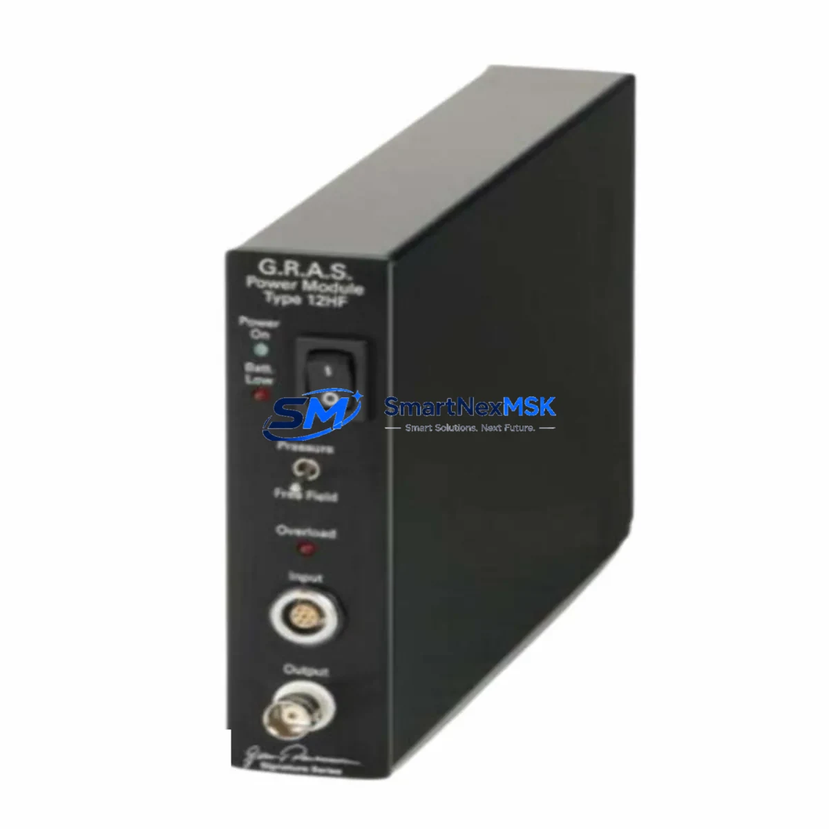
| SKU / Part Number | G.R.A.S. 12HF |
| Brand / Series | SIGNATURE SERIES |
| Module Type | High-Frequency Switching PLC Power Module |
| Mounting Interface | DIN Rail / Backplane Slot Compatible |
| Input Voltage Range | 85–264 VAC / 100–370 VDC (wide-range) |
| Output | Regulated DC (24 VDC typical, verify per system spec) |
| Replacement Compatibility | Compatible with legacy SIGNATURE SERIES control racks and equivalent third-party backplane configurations |
| Communication Interface | Passive power supply — no protocol dependency |
| Installation Requirement | Verify terminal block pitch, connector polarity, and output load capacity before installation |
| Commissioning Notes | Confirm output voltage under load; check for inrush current compatibility with downstream I/O modules |
| Warranty | 12-Month Warranty from date of shipment |
| Origin | China (CN) |
Retrofit Planning for Existing Automation Systems
Successful integration of the G.R.A.S. 12HF into a legacy control system requires a structured pre-installation assessment. Engineers should begin by auditing the existing power budget across the control cabinet. In a typical retrofit scenario, the power module feeds a rack that may host a combination of digital input modules, analog output modules, and communication interface cards — all of which draw regulated DC power from the backplane bus. Undersizing the replacement power supply is one of the most common causes of intermittent faults after a retrofit.
Before removing the original unit, document the terminal wiring layout, including L, N, PE, and DC output terminals. Many legacy systems use non-standard terminal block pitches or proprietary connector housings. Confirm that the G.R.A.S. 12HF terminal configuration matches or can be adapted using appropriate ferrule connectors or terminal adapters without modifying the existing cable harness.
In systems where the power module is co-located with a CPU module or a communications processor — such as a Profibus DP master card, an Ethernet/IP adapter, or a Modbus RTU gateway — the power sequencing during startup must be validated. Some controller platforms require the power supply to reach stable output before the CPU module begins its initialization cycle. Failure to account for this can result in program load errors or watchdog faults on first power-up after the swap.
For installations involving a multi-rack configuration, where the G.R.A.S. 12HF feeds a local rack while a remote I/O rack is connected via a rack expansion cable or a fiber-optic link module, verify that the local power supply capacity is sufficient to support the expansion interface card’s current draw in addition to the local I/O load. Expansion backplanes and their associated rack bus termination resistors can introduce additional load that is often overlooked during initial sizing.
HMI panels connected to the same control cabinet — whether a standalone operator panel, a touch-screen terminal, or a panel-mounted display unit — typically draw power from a separate 24 VDC rail. However, in compact cabinet designs, this rail may share the same power supply as the PLC rack. Confirm load segregation before commissioning to avoid voltage droop affecting HMI communication stability.
Programming cable access is another practical consideration during retrofit. If the CPU module requires a direct serial or USB programming connection for program verification after the power module swap, ensure the programming cable and software version are available on-site before the maintenance window begins. Re-uploading or verifying the ladder logic program after a power cycle is standard practice and should be included in the retrofit checklist.
Downtime Control During System Migration
Minimizing production downtime during a power module replacement requires advance preparation and a disciplined execution sequence. The recommended approach is to perform a full program backup from the CPU module to an offline storage device — either via the programming software or using the controller’s built-in memory card slot — before any hardware is disturbed. This ensures that if the CPU loses its program during the power interruption, recovery is immediate and does not depend on remote access to the engineering workstation.
Where the process allows, a hot-standby or redundant power supply configuration should be evaluated before committing to a single-module replacement. In systems where redundancy is not available, coordinate the maintenance window with the production schedule to align with planned downtime or shift changeovers. Communicate the expected outage duration to the operations team and confirm that all field devices — including actuators, sensors, and safety interlocks — are in a safe state before de-energizing the cabinet.
During the physical swap, label all terminal connections before disconnection and photograph the wiring layout. Re-energize the system in stages: first confirm the power supply output voltage is within specification before reconnecting the backplane load. Monitor the CPU module’s status LEDs during the first power-up cycle to confirm normal initialization. Check all I/O module status indicators and verify that the HMI communication link is re-established before releasing the system back to production.
Post-installation, run a functional verification test covering all critical I/O points, communication links, and control loops. Document the as-installed configuration, including the new module’s serial number and installation date, to support future maintenance planning and warranty claims under the 12-month warranty coverage.
Retrofit Support FAQ
Q1: Is the G.R.A.S. 12HF a direct drop-in replacement for my existing power module?
The G.R.A.S. 12HF is designed as a retrofit-compatible replacement for SIGNATURE SERIES control system power modules. Before installation, verify the output voltage rating, terminal block configuration, and physical dimensions against your existing unit. In most cases, the module installs without modification to the existing wiring or mounting hardware. If your system uses a non-standard connector, a terminal adapter may be required.
Q2: What commissioning steps are required after installation?
After installing the G.R.A.S. 12HF, measure the output voltage under load before reconnecting the backplane. Confirm that the CPU module initializes correctly and that all I/O modules report normal status. Verify communication links — including any Profibus, Modbus, or Ethernet/IP connections — are re-established. Perform a full I/O functional test and compare against the pre-maintenance baseline before returning the system to automatic operation.
Q3: How do I verify wiring and terminal compatibility before ordering?
Refer to the existing power module’s nameplate and wiring diagram to confirm terminal pitch, connector type, and output polarity. Cross-reference with the G.R.A.S. 12HF datasheet. If you require technical confirmation, contact our sales team with your existing module’s part number and we will provide a compatibility assessment prior to shipment.
Q4: What does the 12-month warranty cover, and how is it claimed?
The 12-month warranty covers manufacturing defects and functional failures under normal operating conditions from the date of shipment. It does not cover damage resulting from incorrect installation, overvoltage conditions, or physical mishandling. To initiate a warranty claim, contact our support team with the order reference, module serial number, and a description of the fault. Replacement or repair will be arranged within the warranty period at no additional cost.
© 2026 SMARTNEXMSK. All rights reserved.
Original Source: https://smartnexmsk.com
Contact: sales@smartnexmsk.com | +86 18259474341