Skynet SNP-PA51 Maintenance-Ready Spare for SNP Automation
The Skynet SNP-PA51 is an original AC-DC power supply module designed for SNP series industrial automation systems. For maintenance engineers managing production lines, control cabinets, or legacy PLC/DCS installations, unplanned power supply failure is one of the most disruptive causes of unscheduled downtime. Stocking a verified SNP-PA51 spare ensures that when a fault is isolated to the power rail, replacement can be completed within a single maintenance window — restoring system availability without waiting on extended lead times.
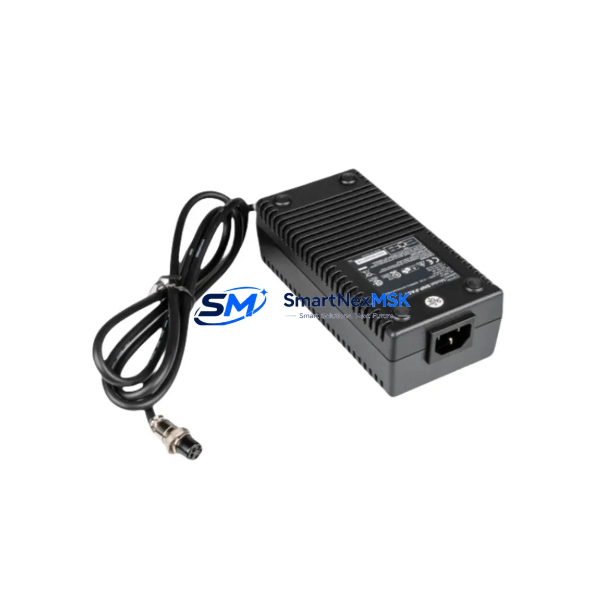
The SNP-PA51 delivers regulated DC output to power SNP series I/O modules, communication modules, and backplane assemblies. Its compact DIN-rail form factor and standardized terminal layout allow direct swap-in without rewiring, making it suitable for both planned preventive maintenance and emergency corrective replacement. Each unit shipped by SMARTNEXMSK is sourced from verified supply channels, function-tested prior to dispatch, and covered by a 12-month warranty.
Spare Maintenance Table
| Parameter | Specification / Detail |
|---|---|
| SKU / Part Number | SNP-PA51 |
| Brand | Skynet |
| Series | SNP Series |
| Product Type | AC-DC Power Supply Module |
| Input Voltage | AC 100–240 V, 50/60 Hz (universal input) |
| Output Voltage | DC 24 V (regulated) |
| Mounting | DIN Rail (35 mm) |
| Compatibility | SNP series I/O racks, backplanes, and communication modules |
| Installation Environment | Industrial control cabinet, IP20 enclosure, 0–55 °C operating range |
| Maintenance Recommendation | Inspect output voltage under load every 12 months; replace capacitors or full unit at first sign of ripple or thermal drift |
| Origin | China (CN) |
| Weight | Approx. 1,500 g |
| Warranty | 12 Months — covers manufacturing defects and functional failure under normal operating conditions |
| Pre-shipment Testing | Output voltage, load regulation, and insulation resistance verified before dispatch |
Maintenance Planning for Continuous Operation
When a maintenance or procurement engineer schedules a control cabinet inspection that includes the SNP-PA51, the scope should extend beyond the power supply itself. A systematic review of the surrounding electrical circuit significantly reduces the risk of repeat failures and secondary faults.
Begin with the AC input side: verify that the upstream circuit breaker or fuse — typically a 2 A or 4 A DIN-rail fuse block — is within its rated interrupting capacity and shows no signs of thermal discoloration. Check the input terminal block for loose connections, which are a common cause of intermittent power faults in high-vibration environments.
On the DC output side, inspect the 24 V distribution terminal strip and any downstream SNP series digital input (DI) and digital output (DO) modules. These modules draw regulated 24 V from the same rail as the SNP-PA51 and are the first components to exhibit erratic behavior when output voltage drops below tolerance. If the SNP-PA51 is being replaced due to output instability, the DI/DO modules should be re-verified after the new unit is installed.
For systems using SNP series analog I/O modules (AI/AO), confirm that signal isolation is intact. Analog modules are sensitive to power rail noise; a degraded power supply can introduce offset errors that appear as sensor drift rather than a power fault. Pairing the SNP-PA51 replacement with an inspection of any signal isolators or signal conditioners in the loop is good practice.
If the control cabinet includes a Skynet SNP communication module — such as a PROFIBUS DP, Modbus RTU, or Ethernet adapter — verify that the module’s power LED and communication status indicators return to normal after the power supply swap. Communication modules are particularly sensitive to power interruptions and may require a cold restart to re-establish network synchronization.
For cabinets with an integrated HMI panel powered from the same 24 V rail, confirm that the HMI boots correctly and that all configured screens and alarm histories are intact. A power supply replacement is also an appropriate time to inspect the HMI’s backup battery if the model includes one.
Finally, check any intermediate relays or solid-state relays (SSRs) in the output circuit. Relay coils powered at 24 V DC can mask a marginal power supply — they may continue to operate at reduced voltage while the downstream PLC I/O reports faults. Replacing the SNP-PA51 without inspecting the relay bank can leave a secondary fault undetected.
A complete spare kit for an SNP series control cabinet typically includes: the SNP-PA51 power supply, one set of SNP DI/DO modules, a spare communication module, a set of DIN-rail fuse holders with rated fuses, and a terminal block repair kit. Maintaining this kit on-site reduces mean time to repair (MTTR) for the most common cabinet-level faults.
Site Replacement Workflow
Step 1 — Fault Isolation: Use the SNP series diagnostic LEDs and any available HMI alarm messages to confirm that the fault is isolated to the power supply rail before removing the SNP-PA51. Measure DC output voltage at the output terminals under load; a reading below 22 V or above 26 V indicates a power supply fault.
Step 2 — Safe Isolation: Switch off the upstream AC circuit breaker and verify with a multimeter that AC input voltage is zero before disconnecting any terminals. Lock out / tag out (LOTO) per site safety procedures.
Step 3 — Removal: Photograph the existing wiring layout before disconnecting. Label AC input, DC output positive, DC output negative, and earth terminals. Release the DIN-rail locking tab and slide the SNP-PA51 free.
Step 4 — Installation: Clip the replacement SNP-PA51 onto the DIN rail. Reconnect terminals in the documented order. Torque terminal screws to the manufacturer’s specified value (typically 0.5–0.6 N·m for 2.5 mm² conductors).
Step 5 — Commissioning: Restore AC power and measure DC output voltage at no load, then under full load. Confirm that all SNP I/O modules, communication modules, and HMI panels power up correctly. Clear any latched alarms in the PLC or DCS and verify that the process returns to normal operating state.
Step 6 — Documentation: Record the replacement date, new unit serial number, and post-installation voltage readings in the equipment maintenance log. Update the spare parts inventory to trigger reorder of a replacement SNP-PA51 for the next maintenance cycle.
Spare Parts Support FAQ
Q1: Is the SNP-PA51 a direct replacement for older SNP series power supply modules?
A: Yes. The SNP-PA51 is designed as a form-fit-function replacement within the SNP series platform. It uses the same DIN-rail footprint, terminal layout, and 24 V DC output specification as earlier SNP power supply variants. No wiring modifications are required for a standard swap-in. If your existing installation uses a non-standard wiring configuration, verify terminal assignments against the SNP-PA51 datasheet before installation.
Q2: What pre-shipment testing does SMARTNEXMSK perform on the SNP-PA51?
A: Every SNP-PA51 unit is tested for output voltage accuracy, load regulation performance, and insulation resistance before dispatch. Units that do not meet specification are quarantined and not shipped. A test report is available upon request for critical infrastructure procurement.
Q3: What does the 12-month warranty cover, and how is a warranty claim processed?
A: The 12-month warranty covers manufacturing defects and functional failure under normal operating conditions (correct input voltage, within rated load, within specified ambient temperature range). To initiate a warranty claim, contact sales@smartnexmsk.com with the order number, unit serial number, and a description of the fault. SMARTNEXMSK will arrange return shipping and dispatch a replacement unit upon fault confirmation.
Q4: Can SMARTNEXMSK support long-term or blanket purchase orders for SNP-PA51 spares?
A: Yes. SMARTNEXMSK supports long-term supply agreements for maintenance-critical spare parts including the SNP-PA51. Blanket orders with scheduled quarterly or annual releases are available for customers managing multi-site SNP series installations. Contact sales@smartnexmsk.com or call +86 18259474341 to discuss volume pricing and delivery scheduling.
© 2026 SMARTNEXMSK. All rights reserved.
Original Source: https://smartnexmsk.com
Contact: sales@smartnexmsk.com | +86 18259474341