SOCAPEL BA4-30-50-310 Maintenance-Ready Spare BA4 Automation
The SOCAPEL BA4-30-50-310 is an original DIN-rail mounted power supply unit engineered for continuous-duty industrial automation environments. Rated for 30–50W output with a wide-range 310V AC input, this unit is a critical backbone component in BA4 Series control panels, machine tool cabinets, and process automation enclosures. When a BA4-30-50-310 fails or degrades, the downstream PLC rack, I/O modules, and field instrumentation lose their regulated DC supply — triggering an unplanned shutdown that can cascade across an entire production line. Stocking a verified original replacement is the single most effective measure a maintenance team can take to compress mean time to repair (MTTR) and protect uptime commitments.
At SMARTNEXMSK, every BA4-30-50-310 unit is sourced from authorized supply chains, individually inspected, and function-tested before dispatch. Each shipment includes a 12-month warranty covering manufacturing defects and output performance. Worldwide delivery is supported, with expedited options available for emergency breakdown orders.
Spare Maintenance Table
| Parameter | Specification |
|---|---|
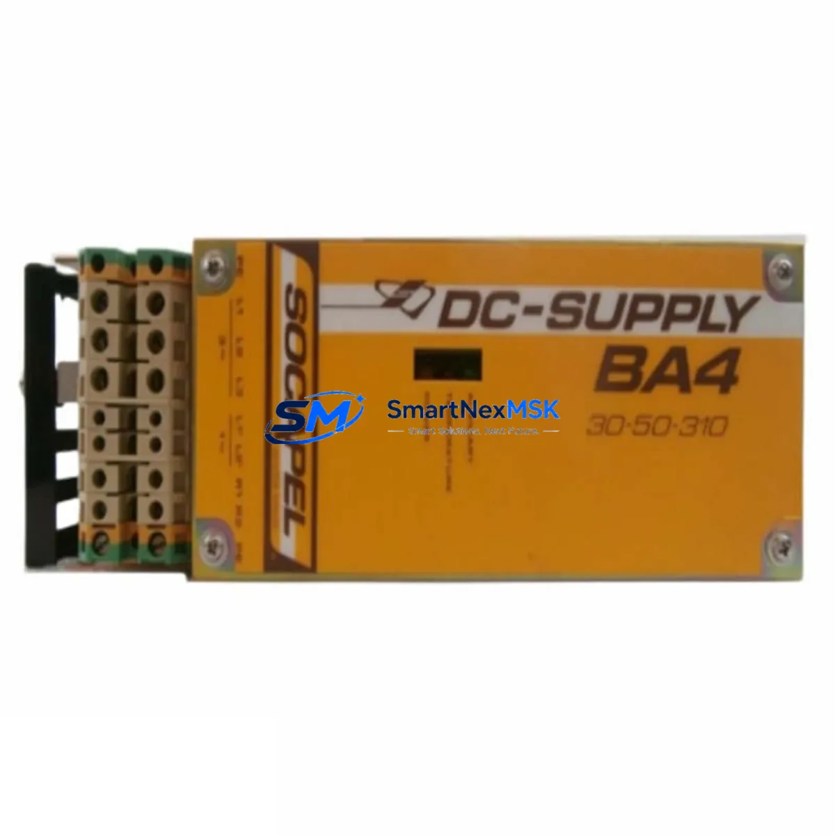
| Part Number / SKU | BA4-30-50-310 |
| Brand | SOCAPEL |
| Series | BA4 |
| Product Type | DIN-Rail Power Supply Unit (PSU) |
| Input Voltage | 310V AC (wide-range) |
| Output Power | 30–50W |
| Mounting | DIN-Rail (EN 60715 / TS 35) |
| Origin | Germany (DE) |
| Series Compatibility | BA4 Series automation panels; compatible with standard 24V DC PLC and I/O bus architectures |
| Application Environment | Industrial control cabinets, machine tool panels, process automation enclosures |
| Protection Class | IP20 (panel-mounted) |
| Operating Temperature | 0°C to +55°C (derated above 40°C) |
| Certifications | CE, UL (series-level); verify specific mark on unit label |
| Warranty | 12 Months — covers output performance and manufacturing defects |
| Pre-shipment Test | Function-tested; output voltage and ripple verified before dispatch |
| Maintenance Recommendation | Replace every 5–7 years or at first sign of output ripple, thermal shutdown, or LED fault indication |
Maintenance Planning for Continuous Operation
A power supply replacement is never an isolated event in a well-managed control cabinet. When a BA4-30-50-310 is pulled for replacement, the maintenance window should be used to inspect and, where necessary, pre-stage spares for the surrounding components that share the same electrical circuit and enclosure.
Begin with the input side: check the upstream miniature circuit breaker (MCB) or fuse block feeding the PSU. A degraded PSU often draws asymmetric inrush current that stresses fuse elements over time — replace any fuse that shows discoloration or has operated near its rated current. Inspect the terminal blocks and DIN-rail bus bars for oxidation, loose ferrules, or heat-discolored insulation, which are common in 310V AC input circuits operating in humid or high-ambient environments.
On the output side, the 24V DC bus feeds the PLC CPU module, digital input (DI) and digital output (DO) modules, and any analog I/O cards in the rack. Verify that the output voltage under full load sits within ±1% of nominal — a sagging rail is a leading indicator of capacitor aging in the PSU. While the cabinet is de-energized, inspect the PLC backplane and I/O bus connectors for bent pins or corrosion, as these faults are often misdiagnosed as PSU failures.
If the BA4 Series panel includes a communications module — such as a PROFIBUS DP adapter, Modbus RTU gateway, or Ethernet/IP coupler — confirm that its isolated 24V supply rail is within spec independently of the main PSU output. Many communication faults during restart are caused by a marginal supply voltage rather than a firmware or network issue. Similarly, any signal isolators or loop-powered transmitters connected to analog input channels should be checked for correct loop current (typically 4–20 mA) after PSU replacement, as a brief supply interruption can reset isolator calibration on some older models.
For panels that include an HMI or operator panel powered from the same 24V bus, verify the HMI boots cleanly and that all screen pages load without communication errors after the PSU is energized. A 24V DC relay module or safety relay in the same enclosure should also be exercised through its full operate/release cycle to confirm coil pickup voltage is within specification. Finally, review the surge protection device (SPD) on the AC input — if the site has experienced lightning events or utility switching transients, the SPD may have sacrificed itself protecting the PSU and should be replaced as a matter of course.
Recommended companion spares to pre-stage alongside the BA4-30-50-310: DIN-rail fuse holders and fuse elements (10×38mm or 5×20mm per panel design), 24V DC coil relay modules, PROFIBUS or Modbus communication interface cards for the BA4 rack, analog signal isolators (4–20 mA loop), DIN-rail terminal blocks (screw or spring-cage), miniature circuit breakers (1–6A, C-curve) for PSU input protection, and 24V DC panel indicator lamps or LED signal towers for status monitoring.
Site Replacement Workflow
Step 1 — Isolation and lockout: Isolate the AC supply to the control cabinet at the upstream MCB. Apply LOTO (lockout/tagout) per site procedure. Confirm absence of voltage on the PSU input terminals with a calibrated multimeter before proceeding.
Step 2 — Documentation: Photograph the existing wiring layout, terminal labeling, and DIN-rail position of the BA4-30-50-310 before disconnection. This is especially important in older systems where as-built drawings may not reflect field modifications.
Step 3 — Removal: Disconnect AC input wiring (L, N, PE) and DC output wiring (V+, V−, GND) at the terminal blocks. Release the DIN-rail latch and slide the unit off the rail. Note the rail position for correct reinstallation of the replacement unit.
Step 4 — Inspection and cleaning: Clean the DIN-rail mounting area. Inspect adjacent components for heat damage or contamination. Replace any damaged terminal ferrules before reconnecting.
Step 5 — Installation of BA4-30-50-310 replacement: Clip the new unit onto the DIN rail. Reconnect AC input and DC output wiring per the original layout. Torque terminal screws to the manufacturer’s specified value (typically 0.5–0.8 Nm for 2.5mm² conductors).
Step 6 — Commissioning: Restore AC supply. Measure output voltage under no-load, then under full load. Confirm the output is within ±1% of 24V DC. Observe the PSU status LED — steady green indicates normal operation. Power up the PLC and I/O modules sequentially and confirm all I/O channels report correctly in the SCADA or HMI system.
Step 7 — Documentation close-out: Update the maintenance log with the replacement date, unit serial number, and post-installation test results. Flag the next scheduled inspection interval (recommended: 12 months or next planned shutdown).
Spare Parts Support FAQ
Q1: Is the BA4-30-50-310 still in production, and can I source it for an aging BA4 Series system?
The BA4-30-50-310 is available as an original spare through authorized distribution channels. SMARTNEXMSK maintains stock specifically to support legacy and end-of-life automation systems where OEM supply has become unreliable. Long-term supply agreements are available for customers managing large installed bases of BA4 Series equipment.
Q2: How do I verify compatibility before installation?
Confirm the input voltage range (310V AC), output power rating (30–50W), and DIN-rail form factor match your existing panel design. Cross-reference the part number on the original unit’s label with BA4-30-50-310. If your panel uses a variant with a different output voltage or connector configuration, contact sales@smartnexmsk.com with your panel drawing or nameplate photo for compatibility confirmation before ordering.
Q3: What does the 12-month warranty cover, and what is the claims process?
The 12-month warranty covers manufacturing defects and output performance deviations from published specifications under normal operating conditions. It does not cover damage caused by incorrect installation, overvoltage events, or physical impact. To initiate a warranty claim, contact sales@smartnexmsk.com with the order number, unit serial number, and a description of the fault. Replacement units are dispatched after fault verification, with return shipping coordinated by SMARTNEXMSK.
Q4: Is pre-shipment testing performed on every unit?
Yes. Every BA4-30-50-310 unit is function-tested before dispatch. Output voltage, ripple, and load regulation are verified under controlled conditions. A test record is available on request. Units are packed in anti-static, shock-absorbing packaging to prevent transit damage. Expedited shipping options are available for emergency breakdown orders requiring next-day or 48-hour delivery.
© 2026 SMARTNEXMSK. All rights reserved.
Original Source: https://smartnexmsk.com
Contact: sales@smartnexmsk.com | +86 18259474341