Square D D8430 Retrofit-Ready Phase Monitoring Relay: Compatible Modernization for Legacy Control Systems
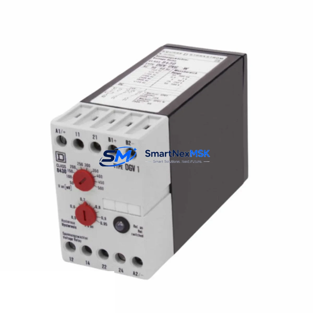
The Square D D8430 is a phase monitoring relay engineered for industrial control environments where legacy Square D D-series protection circuits remain in service. As production lines age and original components reach end-of-life, the D8430 serves as a verified retrofit-ready replacement that preserves existing wiring configurations, terminal layouts, and control logic without requiring a full panel redesign. For facilities managing aging motor control centers (MCCs), distribution boards, or multi-zone automation cabinets, sourcing a tested D8430 unit is often the most cost-effective path to restoring protection continuity and avoiding unplanned downtime.
This relay monitors three-phase voltage for conditions including phase loss, phase reversal, phase imbalance, and undervoltage — all critical fault modes in pump stations, compressor rooms, conveyor systems, and HVAC plant rooms. When integrated into a Square D QO or I-Line panelboard environment alongside compatible circuit breakers and motor starters, the D8430 provides a complete protection layer that satisfies both OEM specifications and modern safety standards.
Upgrade Compatibility Table
| Parameter | D8430 Specification | Retrofit Notes |
|---|---|---|
| Brand / Series | Schneider Electric / Square D — D-Series | Direct replacement for legacy Square D phase relay positions |
| Function | 3-Phase Voltage Monitoring (Loss, Reversal, Imbalance, Undervoltage) | Verify relay output wiring matches existing contactor coil circuit |
| Mounting | DIN Rail / Panel Mount | Confirm DIN rail pitch and panel cutout dimensions before installation |
| Terminal Compatibility | Screw-type terminals; standard pitch | Re-use existing ferrule-terminated conductors where possible |
| Supply Voltage | 3-phase line voltage sensing (refer to nameplate) | Confirm input voltage range matches site supply (380V / 400V / 480V) |
| Output Contact | SPDT relay output | Map N/O and N/C contacts to existing control circuit schematic |
| Communication | Hardwired relay output (no fieldbus) | No protocol migration required; integrates with existing hardwired interlock chains |
| Common Replacement Path | Replaces failed or obsolete Square D D-series phase relays | Cross-reference with Square D RM17TG00 or equivalent for alternative upgrade path |
| Pre-Shipment Testing | Function-tested before dispatch | Includes basic energization and trip-point verification |
| Warranty | 12-Month Warranty | Covers manufacturing defects and functional failure under normal operating conditions |
Retrofit Planning for Existing Automation Systems
Successful D8430 retrofits begin with a thorough audit of the existing control cabinet. Before removing the failed or obsolete relay, photograph the terminal wiring, record the conductor labels, and note the relay’s position within the interlock chain. In most Square D MCC configurations, the phase relay output feeds directly into the coil circuit of a Square D LC1 or TeSys D contactor, or into the auxiliary input of a Schneider Electric Altivar variable frequency drive (VFD). Confirming this downstream load is essential before energizing the replacement unit.
For panels that also house a Square D PowerPact or Compact NSX molded case circuit breaker (MCCB) as the upstream protection device, verify that the D8430’s trip response time is coordinated with the MCCB’s instantaneous trip curve. Miscoordination can result in nuisance tripping or, worse, delayed fault clearance. Where the original panel design included a Square D Zelio Logic smart relay or a Modicon M221 compact controller managing the start/stop sequence, the D8430’s output contact must be wired into the correct digital input channel and the associated ladder logic rung must be validated after replacement.
In systems where a Schneider Electric Magelis HMI or a third-party SCADA panel displays phase fault alarms, the alarm bit mapped to the D8430’s output must be re-confirmed after installation. If the original relay used a normally-closed (N/C) contact for the healthy-state signal and the replacement unit’s N/C contact has a different terminal designation, the HMI alarm logic may invert — a common commissioning oversight that causes false “phase fault” indications on the operator screen.
For I/O-intensive panels that combine the D8430 with a Schneider Electric TM3 expansion module or a Modicon STB distributed I/O island, ensure that the relay’s output is wired to a discrete input channel rated for the relay’s contact voltage. Where the original design used a Square D XPSAF safety relay in the same cabinet for emergency-stop monitoring, the D8430 retrofit must not disturb the safety relay’s wiring or bypass its monitored circuit — a critical compliance point for machinery directive conformance.
Finally, if the panel includes a Square D PowerLogic PM5000 series power meter for energy monitoring, the D8430 retrofit provides an opportunity to cross-check the meter’s phase sequence detection against the relay’s phase reversal trip setting, ensuring both devices agree on the site’s phase rotation before the system is returned to service.
Downtime Control During System Migration
Minimizing production downtime during a D8430 replacement requires a structured hot-swap protocol. Begin by scheduling the replacement during a planned maintenance window and preparing a pre-tested spare unit in advance. Before de-energizing the panel, export or photograph the current PLC program from the associated Modicon M221 or M241 controller to a USB drive or programming laptop running EcoStruxure Machine Expert, ensuring the program backup is verified before any wiring is disturbed.
During the physical swap, use insulated terminal screwdrivers and follow a numbered disconnection sequence that mirrors the terminal photograph taken during the audit phase. Re-terminate conductors in the same sequence, torque terminals to the manufacturer’s specification, and perform a point-to-point continuity check before re-energizing. After power-up, simulate a phase loss condition using a test switch or by temporarily opening one phase at the upstream MCCB to confirm the D8430 trips correctly and the downstream contactor de-energizes as expected.
Where the control system includes a Schneider Electric Altivar Process ATV600 or ATV900 drive, verify that the drive’s “input phase loss” detection is disabled or coordinated with the D8430’s trip delay to prevent simultaneous fault responses that could complicate fault diagnosis. Restore the PLC program, confirm HMI alarm states, and run the process through one complete cycle before releasing the system to production. Total replacement time for a well-prepared team is typically under two hours, keeping unplanned downtime to a minimum.
Retrofit Support FAQ
Q1: Is the D8430 a direct drop-in replacement for my existing Square D phase relay?
In most D-series panel configurations, yes. The D8430 shares the same terminal layout and DIN rail footprint as the original Square D phase monitoring relay it replaces. However, always verify the supply voltage range, output contact configuration (N/O vs N/C), and trip delay settings against your original panel schematic before installation. If your panel uses a different Square D relay model in the same position, cross-reference the datasheets to confirm pin-for-pin compatibility.
Q2: What commissioning steps are required after installation?
After wiring, energize the relay and confirm the “healthy” LED or output contact is in the correct state with all three phases present and balanced. Then simulate each fault condition — phase loss, phase reversal, and imbalance — using a test procedure appropriate for your site. Confirm that the downstream contactor or drive responds correctly to each trip. Finally, verify that any HMI alarm pages and PLC fault bits reflect the correct relay state before returning the system to automatic operation.
Q3: Can the D8430 be used with variable frequency drives (VFDs) in the same panel?
Yes, with coordination. The D8430 monitors the incoming supply voltage upstream of the VFD. Since a VFD generates its own output frequency independently of the input phase, the relay should be wired to monitor the supply side, not the drive output. Ensure the relay’s trip delay is set long enough to avoid nuisance trips during VFD start-up inrush, and coordinate with the drive’s built-in input phase loss detection to avoid conflicting fault responses.
Q4: What does the 12-month warranty cover?
The 12-month warranty covers manufacturing defects and functional failure under normal operating conditions from the date of shipment. Each unit is function-tested before dispatch, including energization and basic trip-point verification. The warranty does not cover damage resulting from incorrect installation, overvoltage events beyond the relay’s rated input range, or physical damage during handling. For warranty claims, contact our sales team with the order reference and a description of the fault observed.
© 2026 SMARTNEXMSK. All rights reserved.
Original Source: https://smartnexmsk.com
Contact: sales@smartnexmsk.com | +86 18259474341