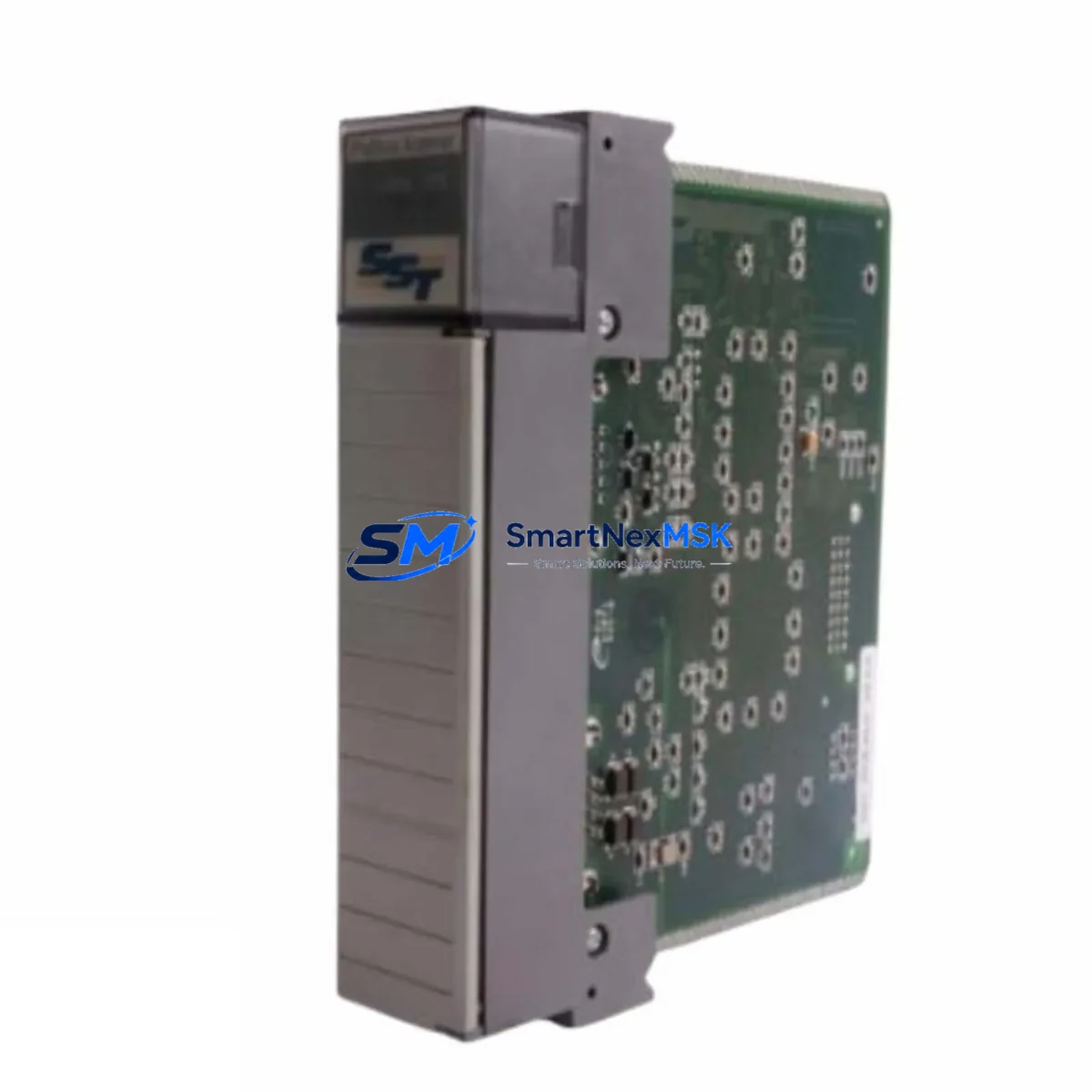
SST SST-PFB-SLC Retrofit-Ready PROFIBUS-DP Scanner for SLC 500 Control Systems
The SST-PFB-SLC is a PROFIBUS-DP master/slave scanner module engineered for direct installation into Allen-Bradley SLC 500 modular chassis. As legacy SLC 500 control platforms approach end-of-life and original PROFIBUS scanner cards become increasingly difficult to source, the SST-PFB-SLC has become the industry-standard retrofit solution for engineers tasked with sustaining PROFIBUS-DP field networks without replacing the entire control system. Whether you are recovering from an unplanned failure, executing a planned upgrade, or migrating a brownfield plant to a more maintainable architecture, this module provides a verified, wiring-compatible replacement path with minimal disruption to existing field devices and program logic.
Sourced directly from authorized distribution channels and subject to full functional testing prior to shipment, every SST-PFB-SLC unit supplied by SMARTNEXMSK is backed by a 12-month warranty and ships with configuration documentation to support rapid commissioning.
Upgrade Compatibility Table
| Parameter | Details |
|---|---|
| Compatible Chassis | SLC 500 modular chassis (4-slot, 7-slot, 10-slot, 13-slot) |
| Slot Installation | Any I/O slot; occupies one slot in the SLC 500 backplane |
| Communication Protocol | PROFIBUS-DP (EN 50170 / IEC 61158), Master Class 1 & 2, Slave mode |
| Baud Rate Support | 9.6 kbps – 12 Mbps (auto-detect) |
| Max PROFIBUS Nodes | Up to 125 slave devices per network segment |
| Backplane Interface | SLC 500 backplane (M0/M1 file, BTR/BTW messaging) |
| Wiring Connector | DB-9 female PROFIBUS connector (standard pinout, no rewiring required) |
| Replacement Compatibility | Direct replacement for discontinued SST-PFB-SLC variants and equivalent third-party SLC PROFIBUS scanners |
| Configuration Tool | SST Network Configuration Tool (Windows-compatible); GSD file import supported |
| Commissioning Notes | Module address, M-file mapping, and BTR/BTW block sizes must be verified against existing ladder logic |
| Warranty | 12 months from date of shipment — covers manufacturing defects and functional failure under normal operating conditions |
Retrofit Planning for Existing Automation Systems
A successful SST-PFB-SLC retrofit begins well before the module arrives on site. Engineers should start by auditing the existing SLC 500 rack configuration — confirming available slot positions, verifying that the 1746 power supply (such as the 1746-P4 or 1746-P7) has sufficient current capacity to support the scanner module alongside existing I/O cards, and documenting the current backplane slot addressing scheme used in the RSLogix 500 program.
On the PROFIBUS network side, retrieve the GSD files for every connected field device — including Siemens ET 200S distributed I/O stations, Danfoss VLT or ABB ACS series variable frequency drives, and any Pepperl+Fuchs or Turck remote I/O blocks — and confirm that the SST Network Configuration Tool has been used to pre-configure the master parameter set before installation. This eliminates the most common source of commissioning delays: mismatched station addresses or incorrect input/output byte lengths in the M0/M1 data files.
For systems that also include a 1747-SN Remote I/O scanner or a 1747-KE DH-485 interface module sharing the same chassis, verify that the combined backplane current draw remains within the power supply’s rated output. If the chassis is already near capacity, consider relocating lower-priority analog I/O modules — such as 1746-NI4 or 1746-NO4I cards — to a secondary chassis connected via a 1747-ASB adapter before installing the SST-PFB-SLC.
Where the existing control cabinet includes an HMI panel — typically a PanelView 550 or PanelView 600 communicating over DH-485 — no changes to the HMI program are required provided the PROFIBUS data is mapped to the same integer file addresses (N-files) that the HMI screens reference. Confirm this mapping in RSLogix 500 before going live to avoid alarm state mismatches on the operator interface.
Finally, if the retrofit is part of a broader migration toward an EtherNet/IP backbone, the SST-PFB-SLC can coexist in the same chassis with a 1747-AENTR EtherNet/IP adapter, allowing the SLC 500 to serve as a protocol bridge during a phased transition — maintaining PROFIBUS-DP field device connectivity while upstream SCADA or MES systems are progressively migrated to Ethernet-based communication.
Downtime Control During System Migration
Unplanned downtime during a PROFIBUS scanner replacement is the primary concern for plant engineers, and the SST-PFB-SLC retrofit process is specifically designed to minimize exposure. The recommended approach is a cold-swap procedure executed during a scheduled maintenance window: power down the SLC 500 rack, remove the failed or obsolete scanner, seat the SST-PFB-SLC in the same slot, restore power, and allow the module to initialize before forcing a program scan.
Before the maintenance window, back up the complete RSLogix 500 project file — including all rung comments, symbol tables, and data file configurations — to a secure offline location. If the original module’s configuration was stored on an external memory card or within the SST configuration utility, export the PROFIBUS master configuration as a project file so it can be reloaded to the replacement module without manual re-entry of station addresses and I/O byte maps.
During commissioning, use the SST Network Configuration Tool’s online diagnostic view to confirm that all PROFIBUS slave devices are responding with correct station addresses and that input/output data exchange is active before releasing the system to production. Monitor the SLC 500’s I/O status bits in RSLogix 500 to verify that no fault codes are latched in the module’s status word. A typical hot-commissioning sequence — from power-on to confirmed network exchange — takes 15 to 30 minutes for an experienced controls engineer familiar with the existing system architecture, keeping total planned downtime well under two hours in most retrofit scenarios.
Retrofit Support FAQ
Q1: Is the SST-PFB-SLC a direct drop-in replacement for the original module in my SLC 500 rack?
Yes. The SST-PFB-SLC uses the standard SLC 500 backplane connector and occupies a single I/O slot, making it physically and electrically compatible with all SLC 500 modular chassis. The PROFIBUS DB-9 wiring connector follows the standard EN 50170 pinout, so existing field cabling does not need to be modified. The only configuration step required is reloading or re-entering the PROFIBUS master parameter set using the SST Network Configuration Tool.
Q2: Will my existing RSLogix 500 ladder logic need to be modified after the replacement?
In most cases, no. If the replacement module is installed in the same chassis slot as the original scanner, the slot-based I/O addressing in your ladder program remains valid. You should verify that the M0/M1 file sizes and BTR/BTW block configurations in your MSG instructions match the SST-PFB-SLC’s default or previously configured values. If the module is installed in a different slot, update the slot address references in all relevant MSG instructions before going online.
Q3: How do I verify wiring and communication link integrity before restarting production?
After installing the module and loading the PROFIBUS configuration, use the SST Network Configuration Tool’s live diagnostic screen to confirm that each slave device is listed as “Data Exchange” status. Check the PROFIBUS cable termination resistors at both ends of the network segment — missing or double termination is the most frequent cause of intermittent communication faults. Verify bus cable continuity and shield grounding at the cabinet entry point before powering up field devices.
Q4: What does the 12-month warranty cover, and what is the process for a warranty claim?
The 12-month warranty covers all manufacturing defects and functional failures under normal operating conditions from the date of shipment. It does not cover damage resulting from incorrect installation, overvoltage, or physical impact. To initiate a warranty claim, contact SMARTNEXMSK at sales@smartnexmsk.com with your order reference, a description of the fault symptom, and any diagnostic data from the SST configuration tool. Replacement or repair will be arranged within the warranty period at no additional cost.
© 2026 SMARTNEXMSK. All rights reserved.
Original Source: https://smartnexmsk.com
Contact: sales@smartnexmsk.com | +86 18259474341