SVS-VISTEK HR16000MTLCPC Spare for HR Series Automation: Spare Replacement & Industrial Downtime Risk Control
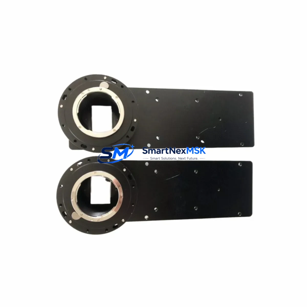
The SVS-VISTEK HR16000MTLCPC is a 16,000-pixel CCD line scan camera from the HR Series, designed for high-throughput industrial inspection systems operating under demanding production conditions. As a maintenance-ready original spare, this unit is sourced, tested, and dispatched to support rapid replacement workflows — minimizing unplanned downtime in web inspection, flat panel display testing, print quality control, and semiconductor wafer scanning lines.
For maintenance engineers managing aging vision systems, the HR16000MTLCPC represents a critical node in the imaging chain. Its Camera Link Full interface, high-resolution 16K pixel array, and precision optical alignment make it a non-trivial component to substitute with generic alternatives. Stocking an original spare — or confirming a verified replacement unit is available on short lead time — is a standard practice in facilities where a single camera failure can halt an entire production line for hours or days.
Procurement engineers sourcing this unit should confirm compatibility with the existing Camera Link frame grabber, illumination controller, and encoder synchronization hardware before dispatch. All units shipped from SMARTNEXMSK undergo pre-shipment functional verification and are covered by a 12-month warranty from the date of delivery.
Spare Maintenance Table
| Parameter | Specification |
|---|---|
| Model / SKU | HR16000MTLCPC |
| Brand | SVS-VISTEK |
| Series | HR Series |
| Sensor Type | CCD Line Scan |
| Resolution | 16,000 pixels (16K) |
| Interface | Camera Link Full |
| Sensor Format | Monochrome (Mono) |
| Origin | Germany (DE) |
| Application Environment | Industrial inspection, web scanning, semiconductor, print QC |
| Compatibility | Camera Link Full frame grabbers; replaces HR Series line scan units |
| Installation | C-mount or F-mount lens interface; encoder trigger input required |
| Maintenance Recommendation | Inspect lens mount, clean sensor window, verify trigger signal integrity at each planned maintenance interval |
| Warranty | 12 Months from date of delivery |
| Pre-shipment Test | Functional verification performed before dispatch |
| Supply Status | In stock / short lead time available |
Maintenance Planning for Continuous Operation
When replacing the HR16000MTLCPC in a live production environment, a thorough inspection of the surrounding system components is essential to prevent repeat failures and ensure the replacement camera performs to specification from day one.
Begin with the Camera Link frame grabber — verify that the frame grabber firmware is current and that the Camera Link Full cable (typically MDR or SDR 26-pin) shows no signs of pin damage or intermittent contact. A degraded cable is a common root cause of image artifacts that are incorrectly attributed to camera failure. Replace the Camera Link cable as a precautionary measure if the system has been in service for more than three years.
Next, inspect the illumination controller and light source. Line scan cameras are highly sensitive to illumination consistency — a failing LED driver or strobe controller will produce banding artifacts even with a new camera installed. Check the illumination power supply output voltage and confirm the strobe trigger signal is synchronized with the camera line rate.
The encoder and trigger interface module should be tested for signal integrity. The HR16000MTLCPC relies on an external encoder pulse to synchronize line acquisition with web or object movement. A faulty encoder, broken shielded cable, or misconfigured trigger delay will result in geometric distortion in the captured image — a fault that is difficult to distinguish from a camera defect without systematic isolation.
For systems integrated with a PLC or motion controller (such as Siemens S7-300/S7-400 series or Allen-Bradley ControlLogix), confirm that the digital I/O module providing the trigger enable signal is functioning correctly. Check the 24 VDC power supply rail feeding the camera and frame grabber — voltage sag under load is a known cause of intermittent camera resets. A dedicated 24 VDC DIN-rail power supply module with adequate current headroom is recommended for vision system circuits.
Inspect the terminal blocks and field wiring in the control cabinet. Loose connections on the power input or trigger signal lines can cause sporadic camera faults that are difficult to reproduce during bench testing. Torque all terminal screws to specification and verify cable shielding continuity.
If the system includes a signal isolator or optocoupler module between the PLC output and the camera trigger input, verify that the isolator is rated for the trigger frequency in use. High-speed line scan applications can exceed the bandwidth of standard industrial optocouplers, causing trigger pulse distortion.
Finally, review the HMI or SCADA display for any logged camera fault codes or communication timeout events that preceded the failure. These logs often reveal whether the failure was sudden (suggesting a hardware fault) or gradual (suggesting contamination, thermal stress, or power instability) — information that guides both the replacement decision and the preventive maintenance schedule going forward.
Site Replacement Workflow
The HR16000MTLCPC is a direct replacement for other SVS-VISTEK HR Series line scan cameras sharing the Camera Link Full interface and the same mechanical form factor. When substituting an older or end-of-life HR Series unit, follow this workflow to minimize downtime and maintain system compatibility:
Step 1 — Pre-replacement verification: Confirm the replacement unit’s SKU, interface type, and pixel count match the system’s frame grabber configuration. Download the current camera configuration file from the vision software (e.g., SVCapture or third-party GigE/CL acquisition software) before powering down the system.
Step 2 — Safe power-down: Isolate the camera power supply and Camera Link interface before disconnecting. Do not hot-swap Camera Link devices — this can damage the frame grabber’s interface circuitry.
Step 3 — Mechanical installation: Mount the replacement camera using the same lens, adapter ring, and focal distance as the original. Do not adjust the lens focus or aperture unless a full optical calibration is planned. Secure all mounting screws to prevent vibration-induced misalignment.
Step 4 — Interface reconnection: Reconnect the Camera Link Full cable, power connector, and trigger/encoder cable. Verify cable seating and locking clip engagement.
Step 5 — Configuration restore: Load the saved camera configuration file into the acquisition software. Verify line rate, exposure time, trigger mode, and gain settings match the original parameters.
Step 6 — Functional test: Run a test scan with a calibration target or reference object. Confirm image geometry, gray-level uniformity, and trigger synchronization before returning the system to production.
This workflow supports a target replacement time of under two hours for a prepared maintenance team, significantly reducing the production impact of an unplanned camera failure.
Spare Parts Support FAQ
Q1: What is the expected service life of the HR16000MTLCPC, and when should I plan a proactive replacement?
CCD line scan cameras in continuous industrial service typically have a functional life of 5–10 years depending on operating temperature, duty cycle, and environmental contamination. We recommend scheduling a proactive spare evaluation after 5 years of service or at the first sign of image quality degradation — whichever comes first. Maintaining one spare unit in stock eliminates the risk of extended downtime during the procurement lead time for a new unit.
Q2: How do I verify compatibility between the HR16000MTLCPC and my existing frame grabber before installation?
Confirm that your frame grabber supports Camera Link Full configuration (80-bit, dual-channel MDR connector). The HR16000MTLCPC outputs a Camera Link Full data stream; frame grabbers configured for Base or Medium mode will not capture the full pixel width. Consult your frame grabber’s Camera Link compliance documentation and verify the acquisition software supports the camera’s pixel clock frequency.
Q3: What pre-shipment testing is performed on each unit, and what does the 12-month warranty cover?
Each HR16000MTLCPC unit dispatched by SMARTNEXMSK undergoes functional verification including power-on test, Camera Link signal integrity check, and image capture validation. The 12-month warranty covers hardware defects and functional failures under normal operating conditions. It does not cover damage resulting from incorrect installation, overvoltage, or physical impact. Warranty claims are supported by our technical team at sales@smartnexmsk.com.
Q4: Can SMARTNEXMSK support long-term or repeat supply of this spare part for multi-site facilities?
Yes. We support blanket order arrangements and scheduled delivery programs for facilities managing multiple production lines or geographically distributed sites. Contact our procurement team to discuss volume pricing, reserved stock agreements, and lead time commitments tailored to your maintenance calendar.
© 2026 SMARTNEXMSK. All rights reserved.
Original Source: https://smartnexmsk.com
Contact: sales@smartnexmsk.com | +86 18259474341