SWAN A-87.213.010 Maintenance-Ready Spare Cerberus Automation
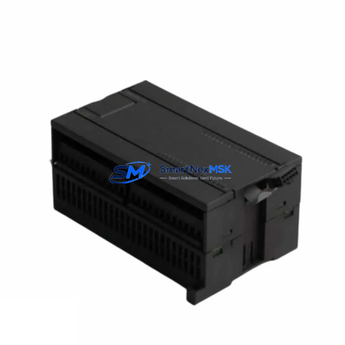
For maintenance engineers and procurement teams managing Cerberus-series fire detection and industrial control systems, unplanned downtime caused by a failed PCB control module is one of the most disruptive events in a facility’s operational calendar. The SWAN A-87.213.010 is an original PCB control module engineered for the Cerberus automation platform, designed to restore system integrity quickly and reliably. Sourced directly from verified supply channels, each unit undergoes pre-shipment functional testing to confirm electrical performance before dispatch. With a 12-month warranty and long-term stock availability, the A-87.213.010 supports both emergency replacement and planned spare parts inventory strategies.
Whether you are executing a scheduled control cabinet inspection, responding to a fault alarm, or building a preventive maintenance kit for an aging Cerberus installation, the A-87.213.010 delivers the compatibility and confidence that industrial environments demand. Its original design ensures seamless integration with existing backplane connectors, I/O wiring harnesses, and communication bus configurations without requiring firmware reconfiguration or hardware adaptation.
Spare Maintenance Table
| Parameter | Specification |
|---|---|
| SKU / Part Number | A-87.213.010 |
| Brand | SWAN |
| Series | Cerberus |
| Product Type | PCB Control Module |
| Origin | Germany (DE) |
| Compatibility | Cerberus series industrial control and fire detection systems |
| Mounting | DIN rail / backplane slot (Cerberus standard) |
| Operating Voltage | 24 V DC nominal (Cerberus bus-powered) |
| Operating Temperature | -10°C to +55°C |
| Application Environment | Industrial control cabinets, fire alarm panels, building automation |
| Pre-Shipment Testing | Functional electrical test performed on every unit |
| Condition | Original spare — new or factory-refurbished |
| Warranty | 12 months from date of shipment |
| Weight | 1,920 g (packaged) |
| Lead Time | In stock — ships within 1–3 business days |
Maintenance Planning for Continuous Operation
A PCB control module failure in a Cerberus system rarely occurs in isolation. When replacing the A-87.213.010, experienced maintenance engineers recommend a concurrent inspection of all interdependent components within the same control cabinet to prevent secondary failures and reduce the risk of repeat callouts.
Begin with the 24 V DC power supply module feeding the Cerberus backplane — voltage ripple or output instability is a common root cause of PCB module degradation. Inspect the backplane connector assembly for oxidation, bent pins, or thermal stress marks that may have contributed to the original fault. Check all field wiring terminal blocks for loose connections, especially on I/O loops that carry detection or control signals.
If the installation includes Cerberus loop driver cards or zone interface modules, verify their firmware revision and communication status on the system bus after the A-87.213.010 is seated. Systems with RS-485 or proprietary Cerberus communication modules should be tested for bus continuity and address conflicts following any PCB swap. Where signal isolators are installed between field devices and the control module, confirm isolation resistance values are within specification.
For installations with integrated relay output modules driving HVAC dampers, suppression systems, or alarm sounders, test each relay coil and contact under load after replacement. Inspect fuse holders and miniature circuit breakers on the 24 V distribution rail — a blown fuse upstream of the A-87.213.010 is frequently overlooked and can cause the replacement module to appear faulty on first power-up. Finally, if the panel includes an HMI operator terminal or annunciator display, confirm that the new module is recognized and that all zone status indicators return to normal before closing the cabinet.
Maintaining a minimum of one A-87.213.010 in your on-site spare parts inventory, alongside a spare power supply module and a set of terminal block connectors, is the most cost-effective strategy for minimizing mean time to repair (MTTR) in Cerberus-equipped facilities.
Site Replacement Workflow
Replacing the SWAN A-87.213.010 in a live Cerberus installation follows a structured sequence to protect system integrity and minimize panel downtime:
1. Isolate and document: Before removal, record the existing module’s address settings, DIP switch configuration, and any LED fault codes displayed. Photograph the wiring harness orientation and terminal labeling. Disable the relevant zone or loop at the panel to prevent spurious alarms during the swap.
2. Remove and inspect: Extract the faulty A-87.213.010 from its backplane slot. Inspect the slot connector for debris or damage. If the backplane shows signs of heat stress or corrosion, clean with appropriate contact cleaner before inserting the replacement.
3. Configure and seat: Transfer address and configuration settings to the new module before installation. Seat the A-87.213.010 firmly into the backplane slot, ensuring all connector pins are fully engaged. Reconnect field wiring terminals in the documented sequence.
4. Power-up and verify: Restore power to the zone. Confirm the module initializes correctly on the Cerberus system bus, that all I/O points report expected status, and that no fault codes are generated. Conduct a functional test of connected field devices — detectors, sounders, or control outputs — before returning the system to normal operation.
5. Update maintenance records: Log the replacement date, module serial number, and test results in the facility’s maintenance management system. Schedule the next inspection interval per the manufacturer’s recommended maintenance cycle.
This workflow is compatible with both direct like-for-like replacement of legacy A-87.213.010 units and migration from earlier Cerberus PCB module variants, ensuring backward compatibility without system reconfiguration.
Spare Parts Support FAQ
Q1: What is the warranty coverage for the SWAN A-87.213.010?
Every A-87.213.010 supplied by SMARTNEXMSK carries a 12-month warranty from the date of shipment. This covers manufacturing defects and functional failures under normal operating conditions. Each unit is tested prior to dispatch to confirm electrical performance.
Q2: How do I verify compatibility before ordering?
The A-87.213.010 is designed for Cerberus-series control systems. Compatibility can be confirmed by matching the part number on the existing module’s label, the system panel documentation, or the original equipment bill of materials. If you require additional confirmation, contact our technical team with your panel model and installation date.
Q3: Can the A-87.213.010 replace earlier or later Cerberus PCB module variants?
In most Cerberus installations, the A-87.213.010 is a direct replacement for modules with the same form factor and bus interface. For cross-generation compatibility, verify the backplane slot type and address range supported by your panel firmware. Our team can assist with compatibility assessment for legacy or upgraded systems.
Q4: What is your recommended spare parts stocking strategy for Cerberus systems?
For facilities with critical uptime requirements, we recommend maintaining at least one A-87.213.010 on-site alongside complementary spares such as a power supply module and terminal connector sets. For larger installations with multiple Cerberus panels, a tiered inventory approach — with fast-access on-site stock and a secondary buffer at a regional warehouse — minimizes MTTR and reduces emergency procurement lead times.
© 2026 SMARTNEXMSK. All rights reserved.
Original Source: https://smartnexmsk.com
Contact: sales@smartnexmsk.com | +86 18259474341