SZCB SZCB-01 Retrofit-Ready Speed Sensor for SZCB Series Control Systems
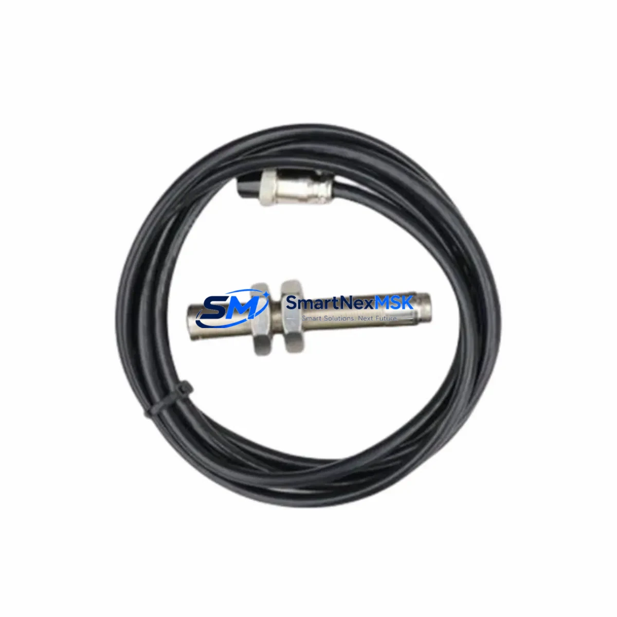
The SZCB SZCB-01 is a precision proximity-type speed sensor engineered for seamless integration into legacy SZCB Series automation platforms. As industrial facilities face increasing pressure to extend the service life of existing control architectures while maintaining production continuity, the SZCB-01 delivers a verified drop-in replacement path that eliminates the need for full panel redesigns or PLC program rewrites. Whether you are modernizing a legacy variable frequency drive cabinet, upgrading a conveyor line speed feedback loop, or restoring a discontinued sensor node in a distributed control system, the SZCB-01 is designed to slot directly into your existing wiring harness and signal chain.
Rated for operation across a wide temperature range of -40°C to +85°C, the SZCB-01 is suitable for demanding industrial environments including steel processing, paper mills, mining conveyors, and chemical plant motor control centers. Its NPN open-collector pulse output is compatible with the digital input modules found across a broad range of PLCs and motion controllers, including Siemens S7-300 DI modules, Mitsubishi MELSEC Q series input cards, and Omron CJ-series high-speed counter units. Engineers replacing legacy Hall-effect or magnetic pickup sensors will find the SZCB-01’s output signal characteristics consistent with standard 12–24 VDC sourcing logic, reducing the need for signal conditioning relays or interposing modules.
Upgrade Compatibility Table
| Parameter | SZCB-01 Specification | Retrofit Notes |
|---|---|---|
| Output Type | NPN Open Collector | Compatible with standard PLC DI modules (12–24 VDC) |
| Supply Voltage | 12–24 VDC | Verify existing panel PSU capacity before swap |
| Operating Temperature | -40°C to +85°C | Suitable for outdoor and high-heat enclosures |
| Connector / Wiring | 3-wire (VCC, GND, Signal) | Match terminal block assignments; confirm shield grounding |
| Mounting Interface | M18 threaded barrel | Check existing bracket thread pitch before installation |
| Communication Protocol | Pulse frequency output | Map to HSC (High-Speed Counter) input on controller |
| Replacement Compatibility | SZCB Series legacy speed sensors | Confirm gear tooth count and sensing gap with original datasheet |
| Commissioning Requirement | Scaling factor verification | Adjust PLC speed calculation block if pulse-per-revolution differs |
| Warranty | 12 Months | Covers manufacturing defects; includes pre-shipment functional test |
Retrofit Planning for Existing Automation Systems
A successful SZCB-01 retrofit begins well before the sensor arrives on-site. The first step is a thorough audit of the existing control cabinet, including the power supply module capacity, terminal block layout, and the DIN rail space available for any supplementary signal conditioning. In many legacy SZCB Series installations, the 24 VDC rail is shared between the speed sensor, proximity switches, and the coil supply for intermediate relays — engineers should verify that the existing SITOP PSU or equivalent power supply unit can sustain the additional inrush current without triggering overcurrent protection on the distribution block.
Terminal wiring is the most common source of commissioning delays during sensor replacement. The SZCB-01 uses a standard 3-wire NPN configuration: brown (VCC), blue (GND), and black (signal output). When replacing an older 2-wire AC proximity sensor or a legacy magnetic pickup coil, the terminal block must be rewired to accommodate the additional ground reference. In installations where the original sensor fed directly into an analog input card — such as a Siemens SM 331 or an Allen-Bradley 1756-IF8 — a pulse-to-analog converter or a dedicated high-speed counter module like the Siemens FM 350-1 or Mitsubishi QD62 may be required to correctly interpret the SZCB-01’s digital pulse train.
Backplane and rack considerations are equally important in modular PLC architectures. If the speed feedback signal is processed by a motion control module mounted on a Siemens ET 200M distributed I/O rack or a Mitsubishi MELSEC Q series base unit, the module address and I/O mapping in the PLC program must be verified against the new sensor’s pulse characteristics. Changes to the pulses-per-revolution value — even minor ones — will propagate errors through speed calculation function blocks, PID loop setpoints, and any HMI trend displays configured to show motor RPM or conveyor belt speed. Before going live, engineers should back up the existing PLC program, document the current HSC scaling parameters, and prepare a rollback procedure in case the new sensor’s output requires recalibration.
For systems that include a PROFIBUS DP or PROFINET communication link between the field device level and the control room, the sensor replacement itself does not affect the network topology — but any changes to the I/O module configuration may require a GSD file update or a hardware configuration download in STEP 7 or TIA Portal. Similarly, in installations using Modbus RTU over RS-485 for remote I/O, the slave address assignments and register mapping should be documented before the retrofit begins to avoid address conflicts during recommissioning. Operators should also verify that the HMI screens — whether running on a Siemens TP700 Comfort Panel, a Weintek MT8000 series, or a standalone SCADA workstation — correctly reflect the updated tag names and engineering unit conversions after the sensor swap.
Downtime Control During System Migration
Minimizing unplanned downtime is the primary operational concern during any sensor replacement on a live production line. The recommended approach for SZCB-01 installation is a planned maintenance window during a scheduled shift changeover or weekend shutdown, with a target replacement time of under 60 minutes for a single sensor node. Before de-energizing the panel, the technician should capture a screenshot or printout of all relevant HMI trend pages, note the current PLC diagnostic buffer status, and confirm that the machine is in a safe, stopped state with all energy isolation procedures (LOTO) completed.
To protect the original program logic, the PLC CPU — whether a Siemens S7-315, a Mitsubishi Q06UDEH, or an Omron CJ2M — should be placed in STOP mode only after confirming that all downstream processes dependent on the speed feedback signal have been safely halted. The existing sensor wiring should be photographed and labeled before removal. After installing the SZCB-01 and restoring power, the technician should use the PLC’s online monitoring function to verify that the high-speed counter input is receiving pulses at the expected frequency before releasing the machine to production. A brief jog test at reduced speed — typically 10–20% of rated RPM — is sufficient to confirm signal integrity and scaling accuracy without exposing the process to full-load conditions.
For critical applications where even a brief interruption is unacceptable, a hot-standby sensor arrangement using a spare SZCB-01 pre-wired to a selector switch on the terminal block can reduce switchover time to under 30 seconds. This approach is particularly effective in continuous process industries such as paper coating lines, extrusion systems, and chemical dosing conveyors where speed feedback loss triggers an emergency stop sequence. All SZCB-01 units shipped by SMARTNEXMSK undergo a pre-shipment functional test to verify output signal quality, ensuring that the replacement unit is ready for immediate installation without bench testing delays.
Retrofit Support FAQ
Q1: Is the SZCB-01 a direct drop-in replacement for all SZCB Series speed sensors?
The SZCB-01 is designed as a functional replacement for the standard SZCB Series proximity-type speed sensors with NPN output. Before installation, confirm that the original sensor’s pulses-per-revolution specification, sensing distance, and supply voltage match the SZCB-01 datasheet. Minor differences in sensing gap or target wheel geometry may require a small mechanical adjustment to the mounting bracket.
Q2: What wiring changes are required when replacing a legacy 2-wire sensor with the SZCB-01?
The SZCB-01 uses a 3-wire NPN configuration. If the original installation used a 2-wire AC inductive sensor, the terminal block must be modified to add a dedicated 0 VDC ground reference for the sensor’s blue wire. The signal wire (black) connects to the PLC digital input terminal, and the brown wire connects to the 24 VDC supply. Ensure the input module’s common terminal is correctly referenced to the same 0 VDC rail.
Q3: How do I verify compatibility with my existing PLC high-speed counter module?
The SZCB-01 outputs a standard NPN pulse signal compatible with most HSC modules, including the Siemens FM 350-1, Mitsubishi QD62, and Omron CJ1W-CT021. Check the maximum input frequency rating of your HSC module against the SZCB-01’s output frequency at maximum shaft speed. If the calculated pulse frequency exceeds the module’s rated input bandwidth, consider reducing the target wheel tooth count or selecting a module with a higher frequency rating.
Q4: What does the 12-month warranty cover, and what pre-shipment testing is performed?
Every SZCB-01 unit supplied by SMARTNEXMSK is covered by a 12-month warranty against manufacturing defects in materials and workmanship, commencing from the date of shipment. Pre-shipment testing includes output signal verification at rated supply voltage, insulation resistance check, and mechanical inspection of the connector and housing. Units that fail any test criterion are quarantined and not shipped. Warranty claims are processed via sales@smartnexmsk.com with proof of purchase and a fault description.
© 2026 SMARTNEXMSK. All rights reserved.
Original Source: https://smartnexmsk.com
Contact: sales@smartnexmsk.com | +86 18259474341