T&B 161-96450-3008 Maintenance-Ready Spare MOC V 2.1 Automation
When a PC controller board fails inside a MOC V 2.1 automation cabinet, every minute of unplanned downtime translates directly into production loss. The T&B 161-96450-3008 is an original-specification PC Controller Board engineered for the MOC V 2.1 series — a platform widely deployed in process control, machine automation, and distributed manufacturing environments across Europe and Asia. Sourcing a verified, tested spare before failure occurs is the single most effective strategy for protecting uptime in aging or mission-critical control systems.
This listing supplies the 161-96450-3008 as a maintenance-ready spare: inspected, functionally tested prior to dispatch, and backed by a 12-month warranty. Whether you are building a proactive spare parts inventory, executing a planned shutdown replacement, or responding to an emergency board failure, this unit ships ready for immediate installation. Origin: Germany (Z+B GmbH). Compatible with MOC V 2.1 control architectures. Global shipping with full export documentation available on request.
Spare Maintenance Table
| Parameter | Specification / Detail |
|---|---|
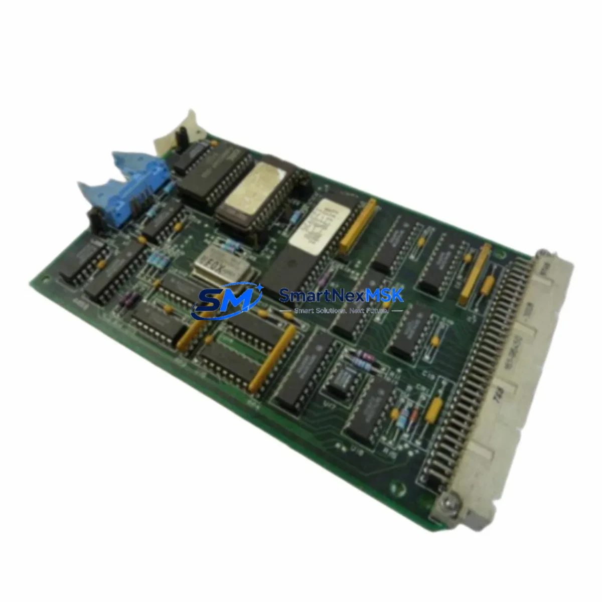
| Part Number | 161-96450-3008 |
| Series | MOC V 2.1 |
| Product Type | PC Controller Board |
| Manufacturer | T&B / Z+B GmbH |
| Country of Origin | Germany (DE) |
| Board Weight | 1,150 g (approx.) |
| Compatibility | MOC V 2.1 control cabinets; drop-in replacement for OEM-installed units |
| Installation | Rack-mount / backplane slot; refer to MOC V 2.1 system manual for slot assignment |
| Application Environment | Industrial automation, process control, machine control panels, DCS sub-systems |
| Pre-shipment Testing | Functional power-on and I/O verification performed before dispatch |
| Condition | Original spare — new or refurbished-to-spec (confirmed at order) |
| Warranty | 12 months from date of shipment |
| Lead Time | In-stock units ship within 1–3 business days; contact for availability |
| Export Documentation | Commercial invoice, packing list, COO available on request |
Maintenance Planning for Continuous Operation
A PC controller board like the 161-96450-3008 sits at the heart of the MOC V 2.1 control architecture. When planning a replacement or conducting a scheduled cabinet inspection, maintenance engineers should treat this board as part of a broader system health review — not an isolated component swap. The following associated components should be inspected or held as co-spares to ensure a complete and reliable restoration of the control loop:
- 24 VDC Power Supply Module — Verify output voltage stability before installing a new controller board. A marginal PSU is a leading cause of premature board failure. Inspect the MOC V 2.1 system power rail and hold a spare power supply unit matched to the cabinet’s load profile.
- Backplane / Rack Assembly — Inspect connector pins and bus integrity on the MOC V 2.1 backplane. Oxidized or bent backplane contacts can cause intermittent faults that mimic board failure.
- Digital I/O Modules — During board replacement, audit all connected DI/DO modules for blown channels or wiring faults. A failed I/O module can generate fault codes that are incorrectly attributed to the controller board.
- Communication Module (e.g., PROFIBUS DP or Ethernet gateway) — If the MOC V 2.1 system communicates upstream to a SCADA or DCS, verify the communication module firmware version is compatible with the replacement board revision.
- Relay Output Modules — Check relay coil resistance and contact condition on any relay output cards wired to the same control cabinet. Welded relay contacts can cause overcurrent conditions that stress the controller board.
- Terminal Blocks and Wiring Harnesses — Inspect all field-side terminal blocks for loose connections, corrosion, or heat damage. Re-torque to specification before powering up the replacement board.
- Signal Isolators / Analog Input Conditioners — For analog-heavy applications, verify that signal isolators feeding the controller board are within calibration. Out-of-range analog signals can trigger false alarms post-replacement.
- Fuse Holders and Protection Fuses — Replace any blown or discolored fuses in the 24 VDC and field-power circuits. A board failure is frequently preceded by a protection fuse event that goes unrecorded.
- HMI Panel / Operator Interface — After board replacement, perform a full HMI communication test to confirm tag mapping and alarm setpoints are intact. Some MOC V 2.1 configurations store parameters locally on the controller board.
- Battery / RTC Module — If the MOC V 2.1 controller board includes a real-time clock or SRAM backup battery, replace the battery as a matter of course during any board swap to prevent program loss on next power cycle.
Holding co-spares for these components alongside the 161-96450-3008 reduces mean time to repair (MTTR) from hours to minutes and eliminates secondary call-outs caused by discovering adjacent failures only after the primary board has been replaced.
Site Replacement Workflow
Replacing the T&B 161-96450-3008 in a live industrial environment requires a structured approach to minimize downtime and avoid configuration loss. Follow this sequence for a safe and efficient swap:
- Pre-shutdown preparation: Back up the current controller program, parameter set, and I/O configuration to an external device or engineering workstation. Confirm the replacement board revision matches the installed unit (check the board label against the MOC V 2.1 system documentation).
- Controlled shutdown: Follow the MOC V 2.1 system shutdown procedure. Do not hot-swap the controller board unless the system documentation explicitly permits it. Isolate the 24 VDC supply and discharge any capacitive loads before handling the board.
- Physical replacement: Remove the failed 161-96450-3008 by releasing the board retention mechanism and sliding it clear of the backplane connector. Install the replacement unit, ensuring full seating on the backplane. Secure all retention clips and re-connect any ribbon cables or field connectors.
- Power-up and verification: Restore 24 VDC supply and observe the board’s status LEDs through the startup sequence. Reload the backed-up program if required. Verify all I/O channels, communication links, and HMI displays are operating correctly before returning the system to production.
- Documentation: Record the replacement in the site maintenance log, including the old board serial number, new board serial number, date, and technician name. Retain the failed board for failure analysis if required under your maintenance program.
This workflow is compatible with both planned maintenance windows and emergency breakdown recovery scenarios. For systems where the MOC V 2.1 controller board has been discontinued by the OEM, the 161-96450-3008 sourced through SMARTNEXMSK provides a long-term supply continuity solution, extending the operational life of legacy control systems without requiring a full platform migration.
Spare Parts Support FAQ
Q1: Is the 161-96450-3008 a new or refurbished board?
We supply both new old-stock (NOS) and refurbished-to-specification units depending on availability. The condition is confirmed at the time of order. All units — regardless of condition — undergo functional testing before shipment and are covered by a 12-month warranty from the date of dispatch.
Q2: How do I verify compatibility with my MOC V 2.1 system before ordering?
Provide your existing board’s part number label (161-96450-3008), hardware revision marking, and the MOC V 2.1 system model number to our technical team at sales@smartnexmsk.com. We will cross-reference against our inventory records and confirm compatibility before the order is processed. We do not ship unverified substitutes.
Q3: What is your recommended spare parts stocking strategy for MOC V 2.1 systems?
For facilities operating two or more MOC V 2.1 cabinets, we recommend holding a minimum of one 161-96450-3008 controller board on-site at all times. Given the age profile of this platform, OEM supply is increasingly constrained. Procuring a spare now — before a failure event — eliminates the risk of extended lead times during an emergency. We can support blanket orders and consignment stocking arrangements for high-volume maintenance programs.
Q4: What does the 12-month warranty cover, and what is the return process?
The 12-month warranty covers functional failure under normal operating conditions. It does not cover physical damage caused by incorrect installation, overvoltage events, or environmental contamination beyond the board’s rated operating range. To initiate a warranty claim, contact sales@smartnexmsk.com with your order number, a description of the fault, and photographic evidence of the installation. We will arrange return shipping and either repair or replace the unit at no additional cost.
© 2026 SMARTNEXMSK. All rights reserved.
Original Source: https://smartnexmsk.com
Contact: sales@smartnexmsk.com | +86 18259474341