TDK 653B-21801 Maintenance-Ready Spare for TAS Automation
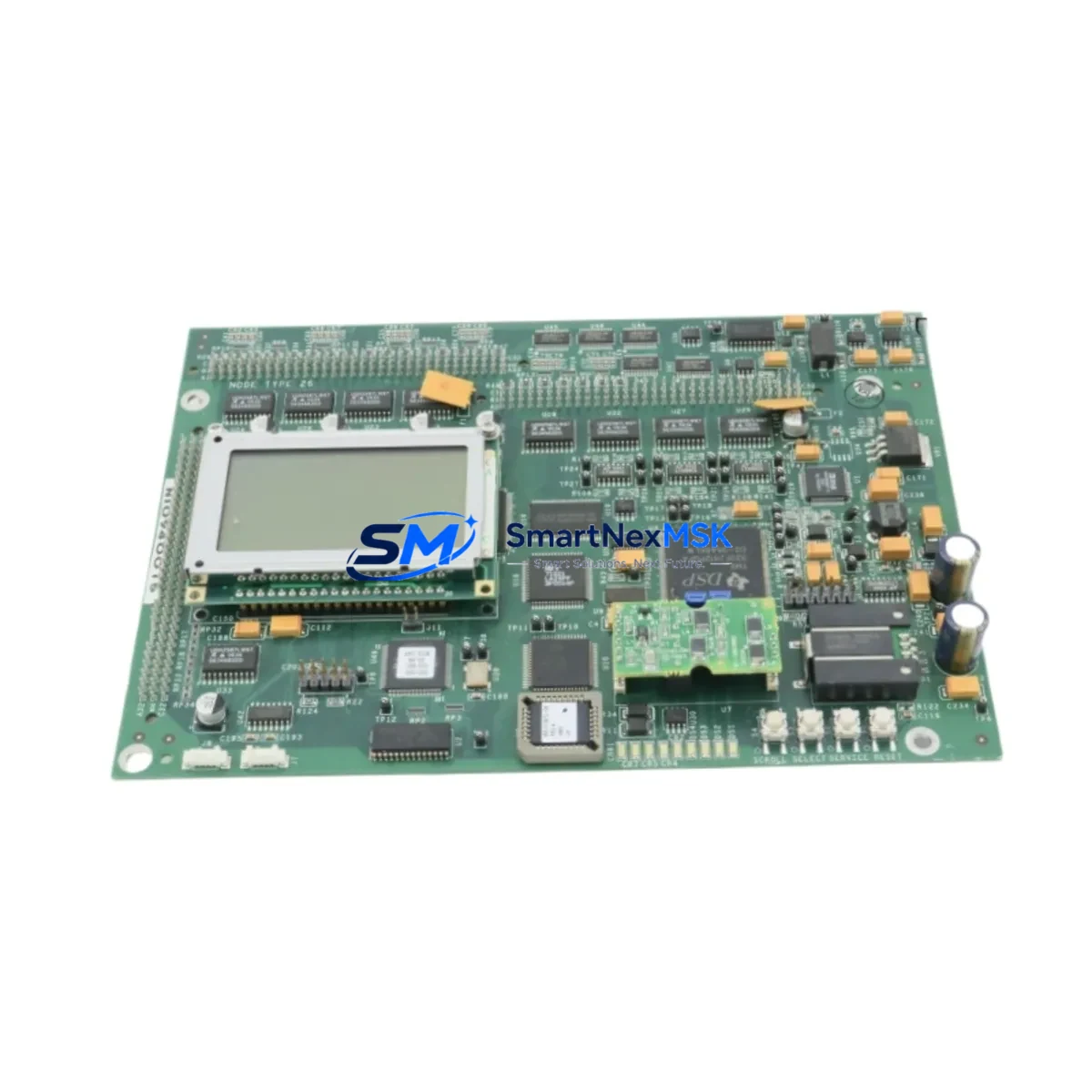
When a FOUP load port system goes down, every minute of unplanned downtime translates directly into yield loss and production schedule disruption. The TDK 653B-21801 — configured as TAS-CPU TAS-MAIN REV.4.10 — is a factory-original CPU control board engineered for the TAS series automation platform. Sourced from verified supply channels, each unit undergoes functional inspection and burn-in verification before dispatch, ensuring that maintenance engineers receive a board that is ready to install, not just ready to ship.
For semiconductor fab environments, cleanroom tool maintenance, and FOUP handling automation, the 653B-21801 serves as the central processing and coordination node of the TAS control architecture. Its replacement is a high-stakes procedure: incorrect substitution or an untested board can introduce new faults, extend downtime, or compromise tool qualification. SMARTNEXMSK supplies this board with full traceability documentation, pre-shipment electrical verification, and a 12-month warranty covering manufacturing defects and functional failure under normal operating conditions.
Spare Maintenance Table
| Parameter | Specification |
|---|---|
| Part Number | 653B-21801 |
| Board Designation | TAS-CPU TAS-MAIN REV.4.10 |
| Brand / OEM | TDK |
| Series | TAS Series |
| Product Type | Industrial CPU Control Board |
| Country of Origin | Japan |
| Application | FOUP Load Port Automation, Semiconductor Tool Control |
| Compatibility | TAS Series load port controllers; verify REV level before installation |
| Board Function | Central CPU / Main Control Logic for TAS platform |
| Installation Type | Direct board replacement; observe ESD precautions |
| Operating Environment | Cleanroom-compatible; controlled temperature and humidity |
| Pre-Shipment Testing | Functional verification and burn-in inspection performed |
| Warranty | 12 Months — manufacturing defects and functional failure |
| Weight | Approx. 800 g |
| Lead Time | In-stock units ship within 3–5 business days |
Maintenance Planning for Continuous Operation
Replacing the TDK 653B-21801 in a live production environment is rarely an isolated task. Maintenance engineers and procurement teams should treat this board replacement as an opportunity to audit the surrounding control architecture and pre-position critical spares. A structured approach significantly reduces the risk of secondary failures following a CPU board swap.
Before powering down the load port station, verify the integrity of the 24 VDC power supply module feeding the TAS control cabinet — a marginal power supply is a common root cause of CPU board failures and will destroy a replacement board if not addressed. Inspect the power distribution terminal blocks and check for signs of thermal stress, loose connections, or corrosion on the input rails.
During the replacement procedure, inspect the I/O interface connectors and ribbon cables linking the CPU board to the sensor and actuator sub-systems. Damaged or intermittently connected I/O cables are frequently misdiagnosed as CPU faults. If the system uses a dedicated communication module for SECS/GEM or EtherCAT interfacing, verify that the module firmware version is compatible with the REV.4.10 board revision before reconnecting.
The TAS platform typically integrates relay output modules for door interlock and pod presence signaling. These relays accumulate contact wear over time and should be inspected or replaced during any planned CPU board maintenance window. Similarly, signal isolation modules protecting the CPU’s analog inputs from sensor noise should be checked for drift or degraded isolation resistance.
For facilities running multiple TAS-series load port stations, it is advisable to maintain at least one spare TAS-IO expansion board and one spare TAS-COMM communication card alongside the 653B-21801 CPU board. These three components form the functional core of the TAS control cabinet and are the most frequently replaced assemblies during scheduled overhauls. Additionally, keep a spare set of fuse holders and blade fuses rated for the TAS cabinet’s protection circuits — blown fuses are often the first symptom of a board-level fault and should be replaced as part of the restoration procedure.
If the system includes an HMI touch panel for operator interface, verify that the HMI communication link to the new CPU board is re-established and that all parameter settings are restored from backup before returning the tool to production. For older TAS installations, consider pre-loading the replacement board with the latest validated firmware image to avoid compatibility issues with updated host software.
Site Replacement Workflow
The 653B-21801 is a direct replacement for earlier TAS-CPU board revisions used in TDK load port systems. When transitioning from an older REV level, confirm that the mechanical mounting pattern, connector pinout, and firmware parameter set are compatible with your specific tool configuration. In most cases, REV.4.10 is backward-compatible with REV.3.x installations, but a firmware parameter backup and restore procedure is strongly recommended.
Step 1 — Isolation: Place the load port in maintenance mode via the host SECS/GEM interface or local HMI. Confirm that no FOUP transfer is in progress and that the pod door is in the closed and latched position.
Step 2 — Power Down: De-energize the TAS control cabinet following the site lockout/tagout procedure. Discharge any residual capacitor voltage on the power supply rails before handling the CPU board.
Step 3 — Board Removal: Document the existing cable routing and connector positions with photographs before disconnecting. Remove the 653B-21801 board using ESD-safe tools and place it in an anti-static bag for failure analysis or return.
Step 4 — Installation: Install the replacement 653B-21801 board, reconnect all cables in the documented sequence, and verify that all connectors are fully seated. Restore firmware parameters from backup.
Step 5 — Verification: Power up the cabinet, confirm that the CPU board initializes without fault codes, and run the TAS self-diagnostic routine. Verify I/O mapping, door interlock operation, and SECS/GEM communication before releasing the tool to production.
This workflow minimizes total downtime to under two hours for a prepared maintenance team, compared to multi-day delays when waiting for unplanned emergency procurement.
Spare Parts Support FAQ
Q1: Is the TDK 653B-21801 REV.4.10 compatible with my existing TAS series load port?
A: The REV.4.10 board is designed for TAS series platforms and is generally compatible with systems previously running REV.3.x boards. We recommend confirming your tool’s serial number and current firmware version with our technical team before ordering to ensure a seamless replacement.
Q2: What does the 12-month warranty cover, and how is a warranty claim processed?
A: The warranty covers manufacturing defects and functional failure under normal operating conditions for 12 months from the date of shipment. To initiate a claim, contact sales@smartnexmsk.com with your order number, a description of the fault, and any available diagnostic logs. We will arrange a replacement or repair at no additional cost.
Q3: How is the board tested before shipment?
A: Each 653B-21801 unit undergoes a pre-shipment functional verification and burn-in inspection. We check power rail integrity, CPU initialization, I/O interface continuity, and communication port functionality. A test report is available upon request for quality-critical procurement processes.
Q4: Can I order multiple units for long-term spare parts inventory?
A: Yes. We support bulk and blanket orders for facilities maintaining strategic spare parts inventories. Volume pricing is available for orders of 3 or more units. Contact our team to discuss lead times, packaging requirements, and long-term supply agreements to protect your production continuity.
© 2026 SMARTNEXMSK. All rights reserved.
Original Source: https://smartnexmsk.com
Contact: sales@smartnexmsk.com | +86 18259474341