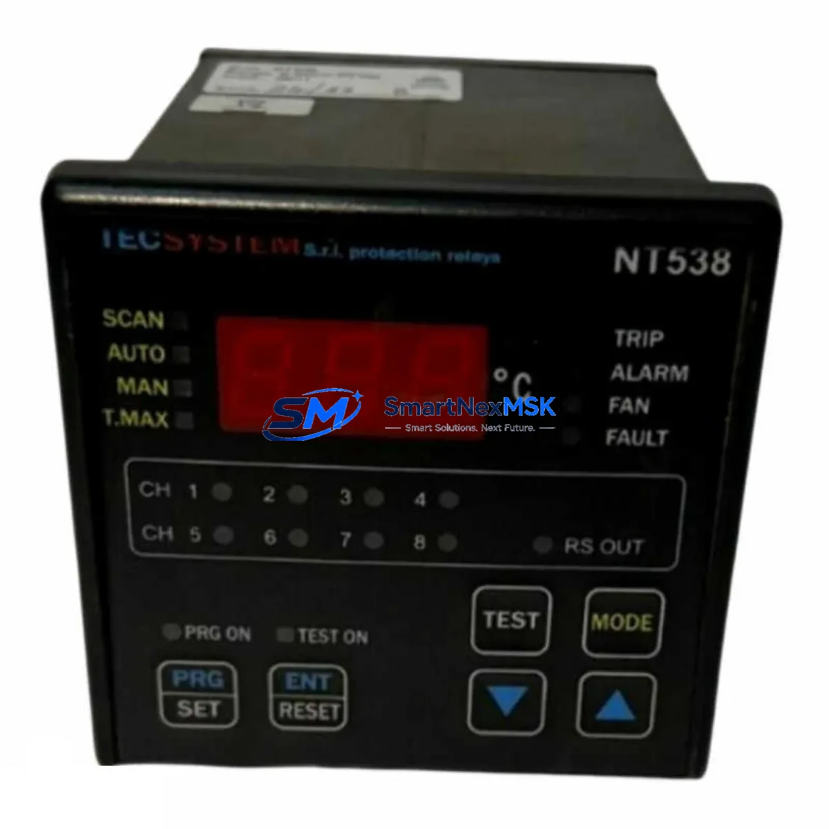
TECSYSTEM NT538 Retrofit-Ready Thermal Protection Relay for NT500 Series Control Systems
The TECSYSTEM NT538 is a precision thermal protection relay engineered for seamless integration into NT500 Series control architectures. Designed with retrofit compatibility as a core specification, the NT538 addresses the growing demand for reliable drop-in replacements in aging industrial automation environments where legacy thermal protection modules have reached end-of-life or are no longer available through standard supply channels. Whether you are upgrading a motor control center, replacing a discontinued protection relay in a DCS-linked cabinet, or modernizing a standalone PLC-driven system, the NT538 delivers the electrical and mechanical compatibility required to minimize engineering rework and reduce total downtime.
Industrial facilities operating NT500 Series panels frequently encounter the challenge of sourcing exact replacements for thermal protection relays that have been discontinued or are subject to extended lead times. The NT538 resolves this by maintaining full backward compatibility with the NT500 Series terminal layout, DIN rail mounting footprint, and standard 24 VDC or 110/230 VAC auxiliary power configurations. Engineers can install the NT538 without modifying existing wiring harnesses, terminal blocks, or cabinet cutouts, which is critical when working within tight maintenance windows or planned shutdown schedules.
Upgrade Compatibility Table
| Parameter | NT538 Specification | Retrofit Notes |
|---|---|---|
| Series Compatibility | NT500 Series | Direct replacement for NT500-family thermal relays |
| Mounting | DIN Rail / Panel Mount | No cabinet modification required |
| Auxiliary Power | 24 VDC / 110–230 VAC | Verify existing PSU output before installation |
| Terminal Interface | Screw-type terminal block | Compatible with existing NT500 wiring harness |
| Communication | Analog / Digital I/O signal output | Confirm PLC input card signal type (NPN/PNP) |
| Protection Class | IP20 (panel-mounted) | Suitable for standard control cabinet environments |
| Replacement Recommendation | Direct swap for discontinued NT500 relays | No firmware or parameter re-mapping required |
| Commissioning | Functional test via PLC diagnostic routine | Verify trip threshold and reset mode post-installation |
| Warranty | 12-Month Warranty | Covered from date of shipment; includes functional defects |
Retrofit Planning for Existing Automation Systems
A successful NT538 retrofit begins well before the module arrives on-site. Engineers should audit the existing control cabinet to confirm the power supply module — typically a TECSYSTEM or third-party 24 VDC rail-mount PSU — can sustain the additional load introduced by the replacement relay alongside co-installed components such as I/O expansion modules, communication gateways, and HMI interface units. In NT500 Series panels that also house analog input modules or RTD/thermocouple signal conditioners, it is essential to verify that the NT538’s signal output type matches the PLC input card’s expected range and polarity.
Terminal wiring should be documented before removal of the legacy relay. Photograph or record the existing terminal block assignments, particularly for the trip output contacts, alarm relay, and auxiliary power feed. The NT538 maintains the same terminal numbering convention as the NT500 Series, but field verification is always recommended — especially in panels that have undergone previous modifications or where as-built drawings may not reflect the current wiring state.
For systems where the NT538 interfaces with a Modbus RTU or Profibus DP communication network, confirm that the module address assignment does not conflict with other devices on the same backplane or communication segment. In multi-drop RS-485 networks, address conflicts between the NT538 and co-installed devices such as motor protection relays, soft starters, or variable frequency drives can cause communication faults that are difficult to diagnose without a protocol analyzer. Where the existing system uses a dedicated communication module or gateway to bridge the thermal protection relay data to the SCADA or DCS layer, verify that the gateway’s device profile supports the NT538’s data map.
Backplane and rack compatibility should also be assessed in systems where the NT538 is installed alongside modular PLC components. In NT500 Series racks that share a common backplane bus with digital output modules, analog output modules, or specialty function modules, confirm that the rack’s power budget accommodates the NT538 without exceeding the backplane’s rated current capacity. If the existing rack is at capacity, a rack expansion unit or a secondary DIN rail section may be required. Programming cables used during commissioning — such as USB-to-RS232 adapters or proprietary TECSYSTEM configuration tools — should be prepared in advance to allow parameter verification and trip threshold adjustment without delays.
HMI screens linked to the legacy thermal relay’s status tags should be reviewed and updated to reflect the NT538’s alarm and trip output designations. In Siemens WinCC, Schneider Vijeo Designer, or similar SCADA environments, tag mapping errors between the old relay and the NT538 can result in false alarm displays or missed trip events. A pre-commissioning simulation using the HMI’s offline test mode is strongly recommended before live energization.
Downtime Control During System Migration
Minimizing production downtime during an NT538 retrofit requires a structured migration plan that preserves the original control logic and field wiring integrity throughout the replacement process. The recommended approach is to complete all pre-installation checks — power budget verification, terminal documentation, address assignment confirmation, and HMI tag review — during a scheduled maintenance window or planned production pause, rather than during an unplanned breakdown response.
Where the process cannot tolerate a full shutdown, a staged migration strategy can be employed: the NT538 is pre-wired and pre-configured on a temporary DIN rail section adjacent to the live panel, with all parameters verified against the original relay’s settings. At the moment of switchover, the legacy relay is de-energized, disconnected, and the NT538 is transferred to the permanent mounting position and connected to the existing terminal block. This approach reduces the live switchover time to under 15 minutes in most NT500 Series cabinet configurations.
After installation, a structured commissioning sequence should be followed: restore auxiliary power, verify communication link status on the PLC diagnostic screen, confirm trip threshold values match the motor’s thermal protection requirements, and perform a manual trip test to validate the relay’s output contacts and the PLC’s response logic. Original program logic stored in the PLC — including ladder rungs, function blocks, or structured text routines that reference the thermal relay’s input tags — should not require modification if the NT538’s I/O signal type matches the legacy relay’s output specification. Retaining the original program backup before any field changes is standard practice and protects against inadvertent logic overwrites during the commissioning phase.
Retrofit Support FAQ
Q1: Is the NT538 a direct drop-in replacement for all NT500 Series thermal protection relays?
The NT538 is designed as a compatible replacement within the NT500 Series family. Terminal layout, DIN rail footprint, and auxiliary power requirements are consistent with NT500 Series specifications. However, engineers should verify the specific variant’s trip class setting, reset mode (manual/automatic), and output contact configuration against the original relay’s datasheet before installation to confirm full functional equivalence.
Q2: What wiring checks are required before installing the NT538?
Prior to installation, document all existing terminal connections including the trip output contacts, alarm relay wiring, auxiliary power feed, and any signal output connections to the PLC input card. Confirm that the NT538’s output signal type (NPN/PNP, normally open/normally closed) matches the PLC input card’s requirements. Verify that the auxiliary power supply voltage matches the NT538’s rated input range.
Q3: How is the NT538 commissioned after installation?
After mechanical installation and terminal connection, restore auxiliary power and confirm the module’s power-on status indicator. Use the PLC diagnostic routine or a dedicated TECSYSTEM configuration tool to verify communication link status and read back the module’s parameter settings. Perform a manual trip test by simulating an overtemperature condition to confirm that the trip output contact operates correctly and that the PLC registers the trip event. Adjust trip threshold and reset mode settings as required to match the motor’s thermal protection specification.
Q4: What does the 12-month warranty cover?
The NT538 is supplied with a 12-month warranty from the date of shipment. The warranty covers functional defects in materials and workmanship under normal operating conditions. It does not cover damage resulting from incorrect installation, overvoltage events, physical impact, or operation outside the module’s rated environmental and electrical specifications. Pre-shipment functional testing is performed on all units to verify trip response, output contact operation, and auxiliary power input before dispatch.
© 2026 SMARTNEXMSK. All rights reserved.
Original Source: https://smartnexmsk.com
Contact: sales@smartnexmsk.com | +86 18259474341