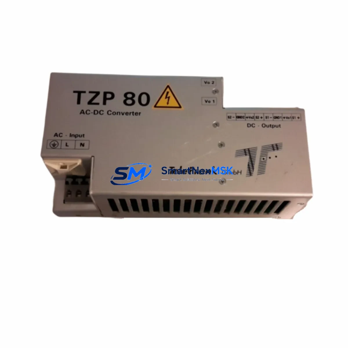
TELEFRANK TZP80-2405/S Retrofit-Ready DIN Rail PSU for TZP Series Control Systems
The TELEFRANK TZP80-2405/S is an 80W, 24VDC / 5A DIN Rail-mount power supply engineered for seamless compatibility with legacy TZP Series control panels and modern retrofit projects. Whether you are replacing an end-of-life unit in a running production line, upgrading an aging control cabinet, or restoring a system after an unplanned failure, the TZP80-2405/S delivers the electrical performance and mechanical form factor required for a low-risk, minimum-downtime swap.
Sourced directly from authorized distribution channels and subject to full pre-shipment functional testing, every TZP80-2405/S unit shipped by SMARTNEXMSK is backed by a 12-month warranty covering manufacturing defects and output performance deviations. Stock is maintained on-hand for immediate dispatch, supporting both emergency replacement orders and planned maintenance schedules.
Upgrade Compatibility Table
| Parameter | TZP80-2405/S Specification | Retrofit Notes |
|---|---|---|
| Output Voltage | 24 VDC | Matches standard 24V PLC logic and I/O bus requirements |
| Output Current | 5 A (80 W continuous) | Verify total load of connected modules before swap; derate to 80% for thermal margin |
| Input Voltage Range | 85–264 VAC / 120–370 VDC | Wide-range input supports both 110V and 220V panel wiring without rewiring |
| Mounting | 35 mm DIN Rail (EN 60715) | Direct drop-in on standard DIN rail; no bracket modification required |
| Terminal Block | Screw-type, 2.5 mm² max | Confirm existing wire gauge; re-terminate if legacy wiring exceeds spec |
| Communication / Signal | DC OK relay output (optional) | Wire DC OK contact to PLC digital input for power-fault diagnostics |
| Replacement Compatibility | TZP Series (TZP80, TZP120 footprint variants) | Confirm terminal pitch and output connector orientation before installation |
| Commissioning Focus | Output voltage trim, load test, DC OK verification | Adjust output trim pot to 24.0 V ±1% under full load before energizing PLC rack |
| Warranty | 12 Months | Covers output voltage deviation, component failure, and thermal shutdown faults |
Retrofit Planning for Existing Automation Systems
A successful TZP80-2405/S retrofit begins well before the unit arrives on site. The first step is an accurate power budget audit of the existing control cabinet. Sum the current draw of every 24VDC consumer: the PLC CPU module, all digital and analog I/O modules mounted on the backplane, any remote I/O expansion racks connected via PROFIBUS-DP or Modbus RTU, and auxiliary devices such as 24VDC solenoid valves, indicator lamps, and relay coils. The TZP80-2405/S provides 5A continuous output, which comfortably supports mid-density PLC racks, but larger configurations — for example, a fully populated 16-slot backplane carrying mixed analog input modules and high-density digital output modules — may require a parallel or higher-capacity supply.
Terminal wiring is the next critical checkpoint. Legacy TZP Series installations often use 1.5 mm² or 2.5 mm² stranded wire terminated with ferrules. Inspect each terminal for corrosion, loose crimps, or insulation damage before re-terminating on the new unit. The L, N, PE (AC input) and +24V, 0V, PE (DC output) terminals on the TZP80-2405/S follow the same left-to-right layout as predecessor TZP models, reducing the risk of miswiring during a hot-swap procedure.
For systems where the power supply feeds a CPU rack — such as a SIMATIC S7-300 or S7-400 series controller, or a comparable third-party platform — confirm that the backplane bus voltage remains stable during the switchover interval. If the PLC program uses retentive memory areas (M bits, DB retain flags) that must survive a power cycle, verify that the CPU’s integrated capacitor or external battery backup module is functional before removing the old supply. Losing retain data during a retrofit can force a full program reload and extended commissioning time.
Communication link continuity is equally important. If the control system uses a PROFIBUS-DP segment with multiple field devices — variable frequency drives, distributed I/O stations, or intelligent motor controllers — a power interruption to the DP master or repeater can cause segment faults that require manual re-initialization of each slave address. Where possible, isolate the PSU replacement to a scheduled maintenance window and pre-configure a spare DP master or communication processor module to accelerate recovery if needed.
For HMI-connected systems, note that operator panels running on the same 24VDC bus will lose power simultaneously with the PLC rack. Pre-save any unsaved HMI recipe data and notify operators to expect a screen blackout. After the TZP80-2405/S is energized and output voltage is confirmed at 24.0 VDC, the HMI will typically reconnect to the PLC automatically via its configured Ethernet or MPI/PROFIBUS link without requiring a manual project download.
I/O expansion considerations: if the system includes remote I/O racks powered by a separate 24VDC branch from the same supply, verify that the new unit’s output current headroom covers both the local rack and the remote expansion. Distributed I/O modules connected via AS-Interface or EtherNet/IP typically draw 0.3–0.8A per node; factor this into the total load calculation. Programming cables and handheld programming devices used during commissioning also draw from the 24VDC bus via USB-to-MPI or USB-to-PPI adapters — disconnect these before performing the final load test to get an accurate baseline reading.
Downtime Control During System Migration
Minimizing unplanned downtime during a PSU replacement requires a structured pre-swap checklist and a clear rollback plan. Before de-energizing the cabinet, upload the current PLC program to an offline backup using the engineering workstation. Confirm the backup file version matches the running program by comparing the program checksum or last-modified timestamp in the project management tool. This step protects against the scenario where the replacement procedure reveals a previously unknown program discrepancy.
Where the process allows, perform a controlled shutdown of the PLC CPU (STOP mode) before removing the old supply. This prevents spurious output signals from reaching field devices — actuators, valves, or drives — during the voltage drop transient. If a controlled stop is not possible due to process constraints, coordinate with the operations team to place the process in a safe hold state and confirm that all safety interlocks are active before proceeding.
The physical swap of the TZP80-2405/S typically takes 10–20 minutes for an experienced technician: isolate AC input, photograph existing terminal wiring, remove the old unit from the DIN rail, mount the new unit, re-terminate all conductors, and restore AC power. After energizing, measure output voltage at the PSU terminals and at the PLC rack bus connector before switching the CPU back to RUN mode. This two-point voltage check catches any wiring error or terminal contact issue before the PLC program resumes control of field devices.
Once the CPU is in RUN mode, monitor the first 5–10 scan cycles for any diagnostic alarms related to I/O module power faults, communication timeouts, or analog input out-of-range conditions. These early-cycle alarms are the most reliable indicator that the retrofit was successful and that all downstream devices have recovered correctly. Document the commissioning results — output voltage reading, load current, DC OK contact status, and alarm log — as part of the maintenance record for the cabinet.
Retrofit Support FAQ
Q1: Is the TZP80-2405/S a direct drop-in replacement for my existing TZP Series supply?
In most TZP Series installations, yes. The TZP80-2405/S shares the same DIN rail mounting footprint, terminal layout, and 24VDC output specification as standard TZP80 variants. Before installation, confirm the output connector orientation and terminal pitch against your existing unit. If your legacy supply has a different output current rating (e.g., a TZP120 variant at 10A), the TZP80-2405/S at 5A may not cover the full load — contact us for a higher-capacity alternative.
Q2: What pre-shipment testing does each unit undergo?
Every TZP80-2405/S dispatched by SMARTNEXMSK is tested for output voltage accuracy (24VDC ±1%), full-load current delivery (5A continuous), input voltage range compliance, and DC OK relay function. Units that fail any parameter are quarantined and not shipped. Test records are available on request for quality-critical applications.
Q3: How do I verify wiring compatibility before installation?
Compare the terminal block diagram in the TZP80-2405/S datasheet against your existing cabinet wiring diagram. Key points: confirm L/N/PE AC input terminal positions, verify +24V and 0V DC output polarity, and check that your existing wire gauge (typically 1.5–2.5 mm²) is within the terminal specification. If your legacy wiring uses ring terminals rather than ferrules, re-terminate with appropriately sized ferrules before connecting to the new unit.
Q4: What does the 12-month warranty cover, and how is a claim processed?
The 12-month warranty covers output voltage deviation beyond ±2%, thermal shutdown under rated load conditions, and component-level manufacturing defects. It does not cover damage from incorrect wiring, overvoltage input events, or physical impact. To initiate a warranty claim, contact sales@smartnexmsk.com with your order number, a description of the fault, and any available measurement data. Replacement units are dispatched within 3 business days of fault confirmation.
© 2026 SMARTNEXMSK. All rights reserved.
Original Source: https://smartnexmsk.com
Contact: sales@smartnexmsk.com | +86 18259474341