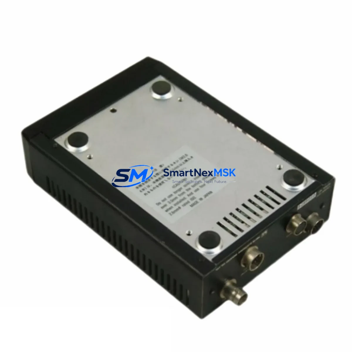
TELI CS3500C Retrofit-Ready Camera Control Unit for CS3500 Control Systems
The TELI CS3500C is a retrofit-ready camera control unit engineered to serve as a direct functional replacement for legacy CS3500 series installations. Designed for industrial imaging and machine vision environments, the CS3500C addresses the growing demand for compatible upgrade solutions where original CS3500 units have reached end-of-life, become discontinued, or are no longer serviceable through standard OEM channels. Whether you are managing a production line camera network, upgrading a quality inspection station, or restoring a failed control node in an existing vision system, the CS3500C provides a reliable, specification-matched path forward without requiring full system redesign.
Industrial facilities operating legacy TELI CS3500 camera control units frequently encounter challenges when sourcing replacement parts: discontinued OEM supply, extended lead times, and the risk of counterfeit components entering the supply chain. The CS3500C resolves these concerns by offering a verified, tested unit with documented compatibility against the CS3500 platform. Each unit shipped by SMARTNEXMSK undergoes pre-shipment functional testing and is covered by a 12-month warranty, giving procurement and maintenance teams confidence in both quality and continuity of supply.
Retrofit planning for the CS3500C begins with a review of the existing installation’s power supply configuration. The CS3500 series typically operates within a defined DC voltage range, and engineers should confirm that the host cabinet’s power module — whether a dedicated 24VDC rail or a shared DIN-rail power supply unit — meets the CS3500C’s input specifications before proceeding. In multi-camera rack installations, the aggregate current draw across all camera control units must be verified against the power supply’s rated output to avoid nuisance tripping or voltage sag during simultaneous camera initialization.
Upgrade Compatibility Table
| Parameter | Legacy CS3500 | CS3500C (Replacement) | Notes |
|---|---|---|---|
| Form Factor | Standard CCU housing | Equivalent form factor | Verify mounting bracket compatibility |
| Interface / Connector | Proprietary TELI multi-pin | Compatible multi-pin | Confirm pin-out against original wiring diagram |
| Power Input | DC regulated supply | DC regulated supply | Verify voltage and current rating at cabinet level |
| Signal Output | Analog / digital video | Compatible signal output | Confirm downstream capture card or frame grabber compatibility |
| Communication Link | Serial / proprietary | Compatible protocol | Validate with host controller or HMI software |
| Installation | Panel / rack mount | Panel / rack mount | No structural modification required in standard cases |
| Retrofit Recommendation | Direct replacement; functional verification recommended post-installation | Test with live camera head before full commissioning | |
| Warranty | OEM (discontinued) | 12-Month Warranty | Covered by SMARTNEXMSK from date of shipment |
Retrofit Planning for Existing Automation Systems
A successful CS3500C retrofit requires systematic review of the surrounding system architecture. In a typical machine vision cabinet, the camera control unit interfaces with a frame grabber board or image acquisition card installed in an industrial PC, a dedicated vision controller, or a PLC-based inspection trigger system. Engineers should document the existing signal routing — including camera head cables, CCU-to-host interface cables, and any sync or trigger wiring — before removing the legacy CS3500 unit.
Terminal block wiring at the CCU’s I/O interface must be mapped against the CS3500C’s terminal layout. In installations where the CS3500 was connected to a PLC digital output module for external trigger signals, the trigger wiring polarity and voltage level should be confirmed to match the CS3500C’s input specifications. Similarly, if the system uses a dedicated lighting controller synchronized to the camera’s exposure cycle, the strobe output signal from the CS3500C must be validated against the lighting controller’s input requirements.
In multi-station vision systems, the CS3500C may operate alongside other TELI camera heads, lens assemblies, and illumination units within a shared control network. Systems that include a TELI camera head paired with a separate lens controller or motorized zoom unit should verify that the CS3500C’s control interface remains compatible with those peripheral devices. Where the original installation included a TELI system controller or a dedicated vision processing unit managing multiple CCUs, the CS3500C’s address configuration — typically set via DIP switch or software parameter — must be assigned to match the original CS3500 unit’s network address to avoid conflicts.
HMI screens configured to display camera status, image quality parameters, or alarm states sourced from the CS3500 may require minor tag remapping if the CS3500C presents data at a different register address or uses a slightly different data structure. Maintenance teams should export and archive the original HMI project file before beginning the retrofit, enabling rapid rollback if commissioning reveals unexpected behavior. In Ethernet-connected vision systems, the CS3500C’s IP address or device ID should be pre-configured on the bench before installation to minimize downtime during the live switchover.
For facilities operating older analog-based inspection lines where the CS3500 fed video signals to a legacy analog frame grabber or a standalone video monitor, the CS3500C’s output format should be confirmed to match the downstream device’s input standard. Where the downstream capture device has been upgraded to a digital interface, this retrofit may present an opportunity to simultaneously upgrade the image acquisition chain, improving image quality and reducing cable complexity across the control cabinet.
Downtime Control During System Migration
Minimizing production downtime during a CS3500C retrofit requires advance preparation and a structured switchover procedure. The recommended approach is to pre-configure the CS3500C on a bench test setup — connecting a representative camera head, verifying signal output, and confirming communication with the host controller — before scheduling the live installation window. This bench validation step eliminates the most common sources of commissioning delay: incorrect address settings, wiring errors, and firmware incompatibilities.
During the live switchover, the original CS3500 unit’s wiring should be documented with photographs before disconnection. Terminal labels or temporary wire markers applied during the bench preparation phase allow technicians to reconnect the CS3500C quickly and accurately. In systems where the PLC program includes camera status interlocks or vision inspection result inputs, the PLC logic should be placed in manual bypass mode during the physical swap to prevent spurious fault conditions from propagating to the production line control system.
After physical installation, the CS3500C should be powered up in isolation — with the camera head connected but the downstream vision processing system in a safe, non-triggering state — to confirm basic power-on behavior and signal presence before enabling the full inspection cycle. Once signal integrity is confirmed, the PLC interlock bypass can be released and the system returned to automatic mode. A short supervised production run of 15–30 minutes is recommended to verify consistent inspection results before returning the line to full unattended operation. This structured approach typically limits total production downtime to under two hours for a single-station CS3500C replacement.
Retrofit Support FAQ
Q: Is the CS3500C a direct drop-in replacement for the original TELI CS3500?
A: The CS3500C is designed as a functional replacement for the CS3500 series camera control unit. In most standard installations, it can be installed using the existing mounting hardware and wiring. We recommend verifying connector pin-out and power supply specifications against your site’s original wiring documentation before installation. Our technical team can assist with compatibility verification prior to shipment.
Q: What commissioning steps are required after installing the CS3500C?
A: After physical installation and wiring reconnection, confirm power-on status, verify camera head signal output, validate communication with the host controller or HMI, and confirm that any PLC trigger or interlock signals are functioning correctly. Where the original system used address-based device identification, ensure the CS3500C’s address is set to match the original CS3500 unit’s configuration. A supervised test run is recommended before returning the line to full automatic operation.
Q: Does the CS3500C come with a warranty, and what does it cover?
A: Yes. Every CS3500C unit shipped by SMARTNEXMSK is covered by a 12-month warranty from the date of shipment. The warranty covers manufacturing defects and functional failures under normal operating conditions. Each unit undergoes pre-shipment functional testing. Warranty claims are handled directly by our technical support team, with replacement or repair options available depending on the nature of the fault.
Q: Can SMARTNEXMSK supply the CS3500C from stock for urgent replacement needs?
A: We maintain inventory of the CS3500C and related TELI camera control components to support urgent replacement and emergency restocking requirements. Standard lead times are confirmed at the time of order. For time-critical situations, please contact our sales team directly to confirm current stock availability and expedited shipping options.
© 2026 SMARTNEXMSK. All rights reserved.
Original Source: https://smartnexmsk.com
Contact: sales@smartnexmsk.com | +86 18259474341