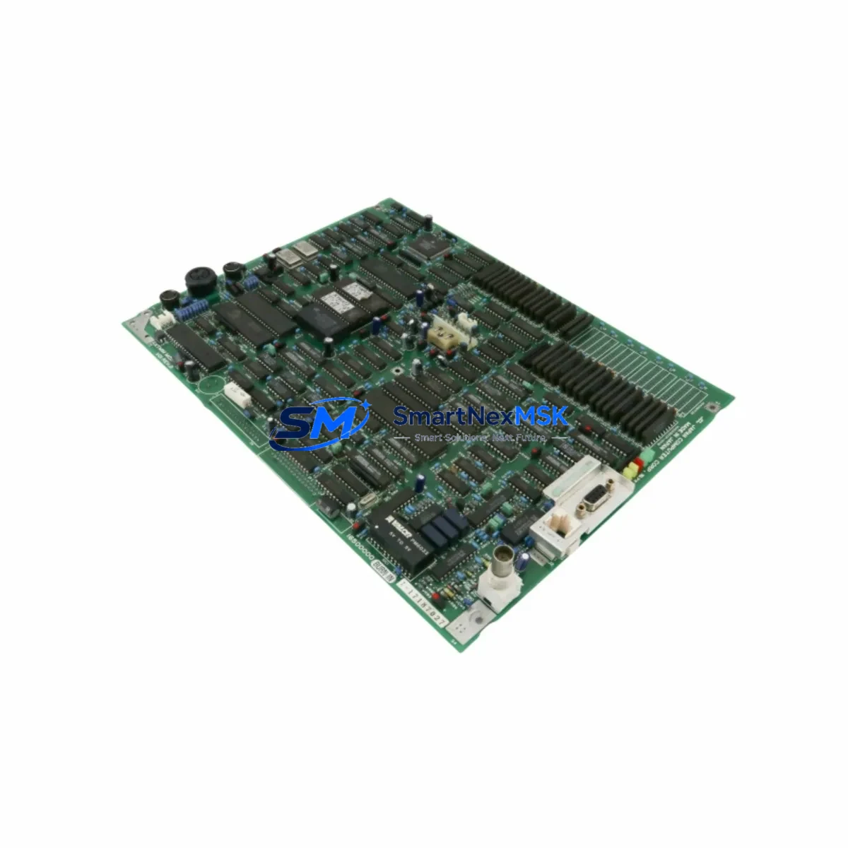
TOKYO COMPUTER MSM020B-0300-NN-M0-CC0 Maintenance-Ready Spare for PLANAPO Automation
The TOKYO COMPUTER MSM020B-0300-NN-M0-CC0 is an original servo PCB assembly designed for the PLANAPO series industrial automation platform. Rated at 200W / 0.95A and cross-referenced as R911295566 and XTMM M05, this board serves as a critical control and drive interface within servo-driven motion systems. For maintenance engineers managing aging PLANAPO installations, securing a verified spare of this PCB is essential to minimizing unplanned downtime and sustaining production continuity.
Whether you are conducting a scheduled annual overhaul, responding to an emergency fault alarm, or building a strategic spare parts buffer for a multi-axis servo cabinet, the MSM020B-0300-NN-M0-CC0 represents a direct, drop-in replacement that preserves original system parameters without requiring firmware reconfiguration or mechanical adaptation.
Spare Maintenance Table
| Parameter | Specification |
|---|---|
| Part Number | MSM020B-0300-NN-M0-CC0 |
| Brand | TOKYO COMPUTER |
| Series | PLANAPO |
| Product Type | Servo PCB Assembly |
| Cross Reference | R911295566 / XTMM M05 |
| Rated Power | 200W |
| Rated Current | 0.95A |
| Origin | Japan |
| Compatibility | PLANAPO Series Servo Drive Systems |
| Installation Type | Direct PCB Replacement (OEM Equivalent) |
| Application Environment | Industrial Control Cabinets, CNC, Servo Motion Systems |
| Maintenance Recommendation | Inspect every 12–18 months; replace on fault code or thermal damage |
| Pre-shipment Testing | Function-tested before dispatch |
| Warranty | 12 Months |
Maintenance Planning for Continuous Operation
When a PLANAPO servo system triggers a drive fault or axis error, the MSM020B-0300-NN-M0-CC0 PCB is frequently the first component to be isolated during fault diagnosis. However, experienced maintenance engineers know that replacing this board in isolation is rarely sufficient for a complete and reliable recovery. A thorough site inspection should accompany any PCB swap.
Begin by verifying the 24VDC control power supply feeding the servo cabinet — voltage sag or ripple at this rail is a common root cause of PCB-level failures that will damage a replacement board if left uncorrected. Next, inspect the servo drive power module and its associated DC bus capacitors for signs of bulging, discoloration, or electrolyte leakage. In PLANAPO multi-axis configurations, the axis expansion backplane and its inter-board connectors should be cleaned and re-seated, as oxidized contacts can cause intermittent communication faults that mimic PCB failure.
The encoder feedback cable and its shielded connector at both the motor and drive ends deserve close attention — damaged shielding introduces noise that corrupts position data and can trigger nuisance faults after a PCB replacement. Similarly, the I/O interface terminal block connecting the servo enable, alarm reset, and speed reference signals should be inspected for loose terminations or corroded contacts.
For systems integrated with a PLANAPO communication module (PROFIBUS, DeviceNet, or proprietary fieldbus), verify that the node address and baud rate settings are preserved after the PCB swap, as some board variants store these parameters locally. If the cabinet includes a regenerative braking resistor unit, check its resistance value and thermal fuse integrity — a failed braking resistor can cause overvoltage faults that are incorrectly attributed to the main PCB.
Procurement engineers building a spare parts inventory for PLANAPO systems should also consider stocking the servo motor thermal sensor connector assembly, control transformer fuses (typically 2A–6A rated), and the 24V switching power supply module as companion spares alongside the MSM020B-0300-NN-M0-CC0. These low-cost components are statistically the most frequent failure points in aging servo cabinets and are often overlooked until they cause a secondary fault during a PCB replacement procedure.
Site Replacement Workflow
Replacing the MSM020B-0300-NN-M0-CC0 in a live production environment requires a structured approach to minimize exposure time and ensure a clean first-time restart. Before beginning, document the existing parameter settings from the servo drive HMI or operator panel — particularly axis gain values, torque limits, and homing offsets — as these may need to be re-entered if the replacement board does not retain non-volatile memory.
Power down the servo cabinet using the main isolator and verify zero-voltage on the DC bus using a calibrated multimeter before touching any internal components. Remove the faulty PCB by releasing the board retention clips and disconnecting all ribbon cables and harness connectors in sequence, photographing each connection point for reference. Install the MSM020B-0300-NN-M0-CC0 replacement, ensuring all connectors are fully seated and the board is secured against vibration.
On power-up, monitor the drive status LEDs and operator display for any residual fault codes. Clear alarm history, restore saved parameters, and perform a low-speed jog test before returning the axis to automatic mode. This workflow typically achieves a full recovery within 45–90 minutes for a prepared maintenance team, compared to 4–8 hours when working without a pre-verified spare on hand.
For facilities managing legacy PLANAPO installations beyond their original design life, the MSM020B-0300-NN-M0-CC0 provides a cost-effective path to system life extension without the capital expenditure of a full drive replacement. Compatibility with original wiring, connectors, and parameter structures means that experienced technicians can execute the swap without specialist vendor support.
Spare Parts Support FAQ
Q1: Is the MSM020B-0300-NN-M0-CC0 a new original part or a refurbished unit?
All units supplied are original TOKYO COMPUTER manufactured parts. Each unit undergoes functional testing prior to shipment to verify electrical performance against OEM specifications. Refurbished or remanufactured units are clearly identified separately and are never substituted without prior customer agreement.
Q2: How do I confirm compatibility with my specific PLANAPO servo drive variant?
Compatibility can be confirmed by cross-referencing the R911295566 reference number and the XTMM M05 designation against your existing drive nameplate or maintenance manual. If you have the original drive model number or cabinet drawing number, our technical team can verify fit before shipment. Contact sales@smartnexmsk.com with your system details for a pre-sale compatibility check.
Q3: What does the 12-month warranty cover, and how is it claimed?
The 12-month warranty covers manufacturing defects and functional failure under normal operating conditions from the date of shipment. It does not cover damage resulting from incorrect installation, overvoltage events, or physical mishandling. To initiate a warranty claim, contact our support team with the order reference and a description of the fault symptom. Replacement or repair is processed within 5–10 business days upon receipt of the returned unit.
Q4: Can you support long-term or blanket purchase orders for PLANAPO spare parts?
Yes. We support scheduled delivery agreements and blanket purchase orders for maintenance teams managing multiple PLANAPO installations. Long-term supply arrangements can be structured to include the MSM020B-0300-NN-M0-CC0 alongside companion spares such as power supply modules, I/O boards, and communication modules, ensuring your spare parts inventory remains aligned with your planned maintenance calendar.
© 2026 SMARTNEXMSK. All rights reserved.
Original Source: https://smartnexmsk.com
Contact: sales@smartnexmsk.com | +86 18259474341