TOSOH QUARTZ 71-00178 RKW24-65R Retrofit-Ready Interferometer for RKW Series Control Systems
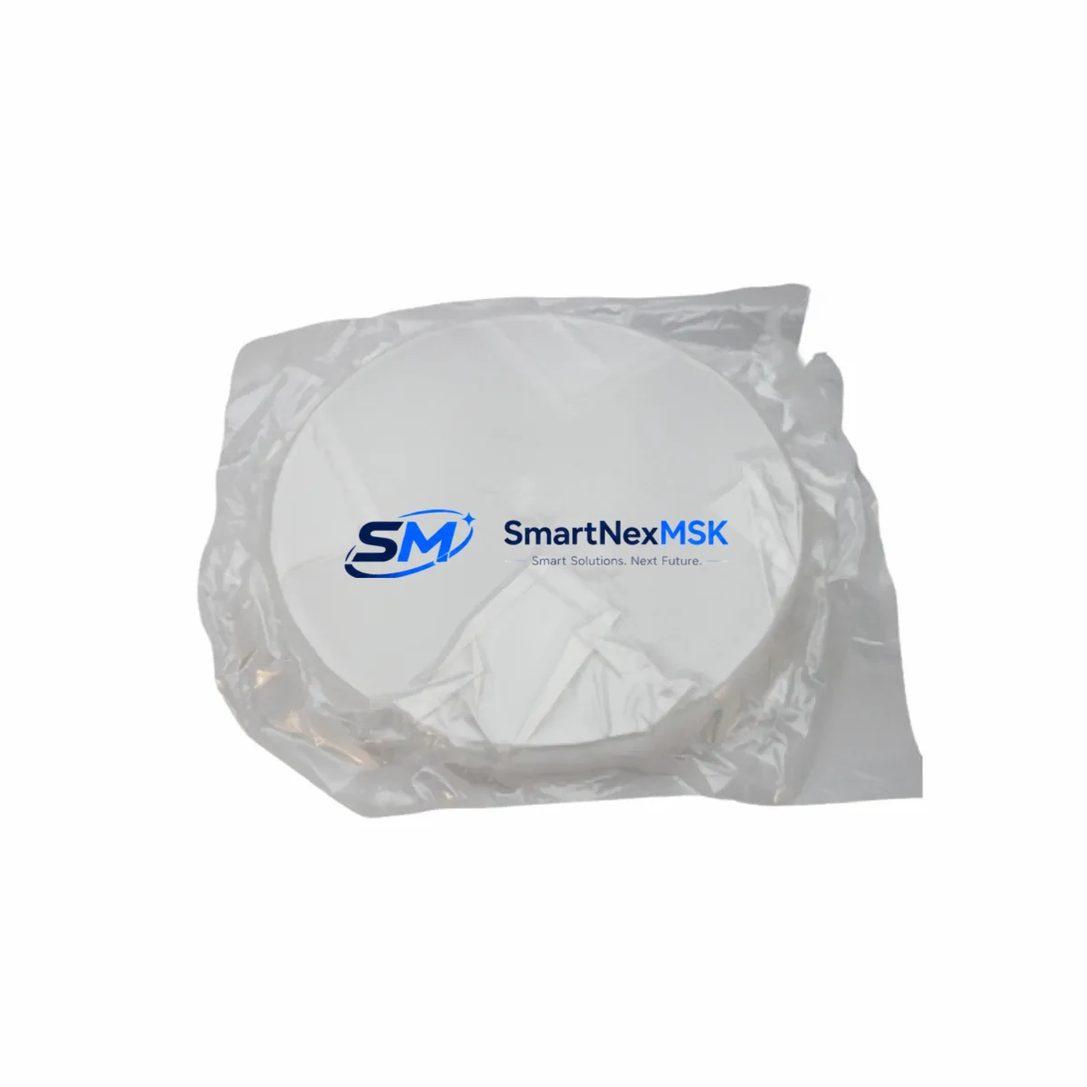
The TOSOH QUARTZ 71-00178 RKW24-65R (also referenced as L55ZV1, J2 K210) is a precision optical interferometer module engineered for seamless integration into RKW series measurement and control platforms. As legacy RKW-series instruments approach end-of-service life, facilities managing semiconductor fabrication, precision metrology, and process control environments increasingly require a verified, drop-in replacement that preserves measurement continuity without requiring full system redesign. This unit fulfills that role — delivering factory-equivalent optical performance, compatible mechanical mounting, and matched signal output specifications to the original RKW24-65R configuration.
Whether your facility is executing a planned upgrade cycle, responding to an unexpected component failure, or consolidating spare-parts inventory ahead of a scheduled shutdown, the 71-00178 RKW24-65R provides a reliable, tested solution backed by a 12-month warranty and pre-shipment functional verification.
Upgrade Compatibility Table
| Parameter | Original RKW24-65R | 71-00178 RKW24-65R (This Unit) | Retrofit Notes |
|---|---|---|---|
| Series Compatibility | RKW Series | RKW Series (full) | Direct series match; no platform reconfiguration required |
| Optical Interface | Standard RKW optical port | Matched optical port geometry | Verify fiber/beam alignment fixture before final installation |
| Mechanical Mounting | OEM bracket pattern | OEM-equivalent bracket pattern | No bracket modification required in standard RKW enclosures |
| Signal Output | Analog / digital per RKW spec | Equivalent output format | Confirm downstream signal conditioning module compatibility |
| Communication Protocol | RKW native bus | RKW native bus compatible | No protocol migration required; existing HMI screens remain valid |
| Power Supply Requirement | Per RKW system PSU spec | Identical power draw | Verify PSU headroom if additional modules have been added to the rack |
| Installation Complexity | — | Low — drop-in swap | Recommended: perform zero-point calibration after installation |
| Warranty | OEM (expired / EOL) | 12 Months | Covers functional defects; excludes physical damage post-installation |
Retrofit Planning for Existing Automation Systems
Integrating the 71-00178 RKW24-65R into an existing RKW-series platform requires a structured pre-installation review. Begin by auditing the system’s power distribution architecture: confirm that the rack-mounted power supply module — typically a dedicated DC regulated unit within the RKW control cabinet — has sufficient residual capacity to support the replacement interferometer without triggering overcurrent protection on adjacent I/O modules or communication cards.
Next, inspect the terminal wiring harness connected to the original RKW24-65R. The signal leads, shield grounding points, and connector locking mechanisms should be documented before removal. In many RKW installations, the interferometer interfaces with a dedicated signal processing board that feeds measurement data to the system’s central controller. If the facility also operates companion modules such as an RKW series analog input card, a dedicated counter/timer module, or an RKW-compatible digital output expansion unit, verify that the replacement unit’s output timing remains within the expected acquisition window of those downstream components.
For systems where the RKW interferometer feeds data into a broader process control loop — for example, a TOSOH QUARTZ precision measurement controller or an integrated RKW series data acquisition chassis — confirm that the measurement scaling factors stored in the controller’s parameter memory do not require recalibration after the module swap. In most cases, if the original calibration coefficients were stored in the controller rather than in the interferometer module itself, the swap is transparent to the control logic.
Where the RKW system communicates upstream to a supervisory SCADA or DCS layer via a serial communication interface module or fieldbus gateway card, no protocol reconfiguration is typically needed, as the 71-00178 RKW24-65R maintains the same bus-level behavior as the original. However, if the facility has previously added a protocol converter module to bridge legacy RKW signals to a modern Ethernet-based control network, verify that the converter’s input signal range remains compatible with the replacement unit’s output characteristics.
Finally, if the RKW system includes a local HMI panel or operator terminal displaying real-time interferometer readings, no screen reconfiguration is required provided the signal scaling is unchanged. Facilities that have upgraded their HMI to a newer touchscreen terminal should confirm that the tag mapping for the interferometer channel remains correctly assigned in the HMI project file before returning the system to production.
Downtime Control During System Migration
Minimizing unplanned downtime during an RKW interferometer replacement begins with preparation, not execution. Before the maintenance window opens, stage the 71-00178 RKW24-65R unit alongside a complete set of replacement terminal connectors, a calibrated optical alignment tool, and a backup copy of the current controller program. If the RKW system is part of a continuous process line, coordinate with production scheduling to align the swap with a planned micro-shutdown or shift changeover — even a 30-minute window is sufficient for an experienced technician to complete a drop-in module replacement.
During the swap, do not power down the entire control cabinet if adjacent process loops can remain active. Isolate only the interferometer circuit using the system’s local isolation switch or by de-energizing the relevant rack slot, if the RKW backplane supports hot-swap or partial power isolation. Preserve the original wiring labels and photograph the terminal block layout before disconnecting any leads — this eliminates reconnection errors that are the most common source of extended downtime in field retrofit operations.
After installation, perform a structured commissioning sequence: power up the module, confirm the status indicator behavior matches the expected initialization pattern, run a zero-point calibration against a known reference, and verify that the downstream signal processing chain is receiving valid measurement data before releasing the system back to automatic control. Document the as-found and as-left calibration values for the maintenance record. This full sequence typically requires less than 45 minutes for a prepared team, keeping total production impact well within acceptable limits for most facilities.
Retrofit Support FAQ
Q1: Is the 71-00178 RKW24-65R a direct drop-in replacement for the original RKW24-65R?
Yes. The 71-00178 RKW24-65R is designed as a form-fit-function replacement for the original RKW24-65R within the TOSOH QUARTZ RKW series platform. Mechanical mounting, optical interface geometry, and signal output format are matched to the original specification. A zero-point calibration is recommended after installation to confirm measurement accuracy in your specific installation environment.
Q2: What pre-shipment testing is performed on this unit?
Each 71-00178 RKW24-65R unit undergoes functional verification prior to shipment, including power-on initialization testing and output signal validation. Units are shipped with a test record confirming operational status. The 12-month warranty covers functional defects identified after installation under normal operating conditions.
Q3: Will I need to reconfigure my HMI or controller program after the swap?
In the majority of RKW series installations, no controller program changes or HMI screen modifications are required. The replacement unit maintains the same bus-level communication behavior as the original. If your facility has made custom modifications to the measurement scaling parameters or has integrated a third-party protocol converter, a brief verification step is recommended to confirm signal continuity through the full control chain.
Q4: What is the lead time and warranty coverage?
Units are available from stock for prompt dispatch. Standard lead time is 3–7 business days depending on destination. All units are covered by a 12-month warranty from the date of shipment, covering manufacturing defects and functional failures under normal operating conditions. Expedited shipping options are available for urgent breakdown situations — contact our sales team directly to confirm availability and arrange priority dispatch.
© 2026 SMARTNEXMSK. All rights reserved.
Original Source: https://smartnexmsk.com
Contact: sales@smartnexmsk.com | +86 18259474341