TRACO POWER HIER466513P0221 T1023-06C Maintenance-Ready Spare: Spare Parts Replacement and Industrial Downtime Risk Control
The TRACO POWER HIER466513P0221 T1023-06C is an original DIN-Rail mounted power supply module from TRACO POWER’s T1023 Series, engineered for continuous-duty industrial automation environments. When a power supply module fails in a live control cabinet, every minute of unplanned downtime translates directly into production loss. Stocking a verified original spare — tested, serialized, and shipped with a 12-month warranty — is the single most effective measure a maintenance team can take to protect system uptime.
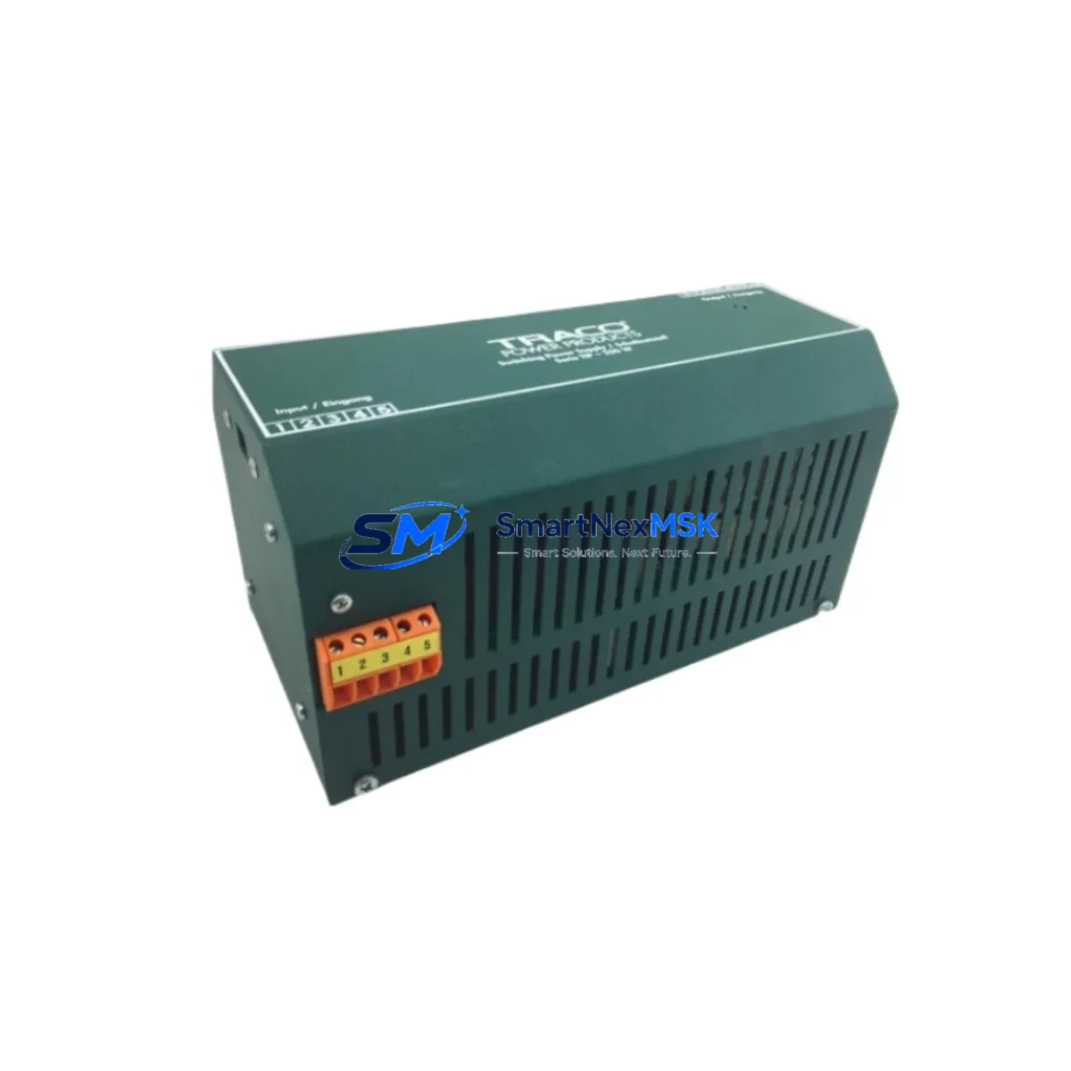
This unit is designed for direct replacement within T1023 Series control architectures. Its compact DIN-rail form factor, wide-input AC range, and regulated DC output make it a standard fit across a broad range of PLC panels, distributed I/O enclosures, and process control cabinets. Maintenance engineers and procurement teams sourcing this module can confirm compatibility by cross-referencing the full SKU HIER466513P0221 T1023-06C against the original panel BOM or nameplate data.
Spare Maintenance Table
| Parameter | Specification |
|---|---|
| Part Number | HIER466513P0221 T1023-06C |
| Brand | TRACO POWER |
| Series | T1023 |
| Product Type | DIN-Rail Power Supply Module |
| Mounting | DIN Rail (EN 60715 / TS 35) |
| Input Voltage | 85–264 VAC / 120–370 VDC (wide range) |
| Output Voltage | 24 VDC (regulated) |
| Output Current | 6 A (nominal) |
| Output Power | 144 W |
| Protection Class | Overload, Short-circuit, Over-voltage |
| Operating Temperature | -25°C to +70°C |
| Compliance | CE, UL, cUL (T1023 Series standard) |
| Country of Origin | Switzerland (CH) |
| Compatibility | T1023 Series panels; direct drop-in replacement for HIER466513P0221 T1023-06C |
| Installation | Snap-on DIN rail; screw terminal wiring; no tools required for rail mounting |
| Application Environment | Industrial control cabinets, PLC panels, DCS marshalling racks, process automation enclosures |
| Maintenance Recommendation | Inspect output voltage under load annually; check terminal torque; verify cooling clearance |
| Warranty | 12 Months — covers manufacturing defects; each unit tested prior to shipment |
Maintenance Planning for Continuous Operation
When scheduling a planned replacement of the HIER466513P0221 T1023-06C, experienced maintenance engineers treat the power supply module as the anchor point of a broader cabinet inspection. A failing or degraded PSU rarely fails in isolation — it stresses downstream components and can mask latent faults across the entire power distribution chain.
During the same maintenance window, technicians should verify the condition of the 24 VDC bus fuses and miniature circuit breakers (MCBs) protecting individual load branches. Fuse holders and blade fuse cartridges rated for the T1023 output current should be inspected for discoloration or thermal stress. Terminal blocks and DIN-rail mounted terminal strips — particularly the power distribution terminals feeding PLC CPU modules and remote I/O racks — should be checked for loose connections and oxidation.
The 24 VDC supply from this module typically feeds TRACO POWER or third-party 24 VDC relay modules, solid-state relay (SSR) assemblies, and signal isolators. Any relay base or relay socket showing contact wear or coil resistance drift should be flagged for replacement during the same outage. Signal isolators and loop-powered transmitter barriers connected to the same 24 VDC rail are also worth inspecting, as voltage ripple from a degraded PSU can introduce measurement drift in 4–20 mA analog loops.
For systems using PROFIBUS DP, PROFINET, or Modbus RTU communication modules mounted in the same cabinet, confirm that the communication module’s power input remains within specification after the PSU swap. RS-485 repeaters and network switches powered from the same 24 VDC bus should be powered down in sequence during the changeover to avoid transient faults on the fieldbus network.
HMI panels and operator terminals drawing power from the same distribution rail should be noted in the maintenance log. A brief power interruption during PSU replacement may trigger HMI reboot sequences — coordinate with the control room operator before isolating the supply. Backplane power connectors on modular PLC racks should be inspected for pin corrosion, particularly in humid or coastal environments.
Finally, review the cabinet’s surge protection devices (SPDs) and EMC filter modules installed on the AC input side. These components protect the T1023-06C from mains transients and should be tested or replaced on a 3–5 year cycle as part of a comprehensive spare parts management program.
Site Replacement Workflow
Step 1 — Confirm Part Identity: Before ordering, verify the full SKU HIER466513P0221 T1023-06C against the panel nameplate, cabinet BOM, or existing module label. Do not substitute based on output voltage alone — confirm output current rating and form factor.
Step 2 — Isolate and De-energize: Isolate the AC input supply to the PSU via the upstream MCB or isolator switch. Verify absence of voltage on both AC input terminals and DC output terminals using a calibrated multimeter before proceeding.
Step 3 — Document Wiring: Photograph or sketch the existing terminal connections — L, N, PE on the AC side; +24V and 0V on the DC output side — before disconnecting. This eliminates re-wiring errors and speeds recommissioning.
Step 4 — Remove and Replace: Loosen terminal screws, disconnect wiring, release the DIN-rail locking tab, and slide the old module off the rail. Snap the replacement HIER466513P0221 T1023-06C onto the rail, reconnect terminals to the documented torque specification (typically 0.5–0.6 Nm for this terminal size), and verify PE continuity.
Step 5 — Power-Up and Verify: Re-energize the AC input. Measure DC output voltage under no-load, then under full load. Confirm output is within ±1% of rated 24 VDC. Check the green LED status indicator. Log the replacement date, technician ID, and new module serial number in the maintenance record.
Step 6 — System Recommission: Restore downstream loads in sequence. Confirm PLC CPU, I/O modules, and communication modules return to normal operating status. Clear any fault codes triggered by the power interruption and notify the control room that the system is back in service.
This structured workflow minimizes total downtime to under 30 minutes for a prepared maintenance team and eliminates the risk of re-wiring errors that can damage the replacement module or connected field devices.
Spare Parts Support FAQ
Q1: Is this an original TRACO POWER module or an aftermarket replacement?
This is an original TRACO POWER HIER466513P0221 T1023-06C module sourced through authorized industrial distribution channels. Each unit is inspected and tested prior to shipment. A 12-month warranty covering manufacturing defects is included with every order.
Q2: How do I confirm compatibility with my existing T1023 Series panel?
Match the full SKU HIER466513P0221 T1023-06C against the module nameplate or your panel BOM. Key parameters to verify are output voltage (24 VDC), output current (6 A), and DIN-rail mounting format. If your panel uses a different T1023 variant, contact our technical team with your panel drawing for confirmation before ordering.
Q3: What is your lead time and how are units tested before shipment?
In-stock units ship within 1–3 business days. Each module undergoes output voltage verification, load regulation testing, and visual inspection before dispatch. Units are packed in anti-static, shock-protected packaging to prevent transit damage. Expedited shipping is available for emergency breakdown situations.
Q4: How should I manage long-term spare parts inventory for T1023 Series systems?
For critical production lines, we recommend holding a minimum of one HIER466513P0221 T1023-06C spare per panel, with a review cycle aligned to your annual planned maintenance shutdown. For aging systems approaching end-of-production status, consider increasing buffer stock to 2–3 units. Our team can support long-term supply agreements and last-time-buy planning for obsolescence-risk components.
© 2026 SMARTNEXMSK. All rights reserved.
Original Source: https://smartnexmsk.com
Contact: sales@smartnexmsk.com | +86 18259474341