VEM MVME6100 CPU4 SPS-A-098744 Maintenance-Ready Spare for MVME6100 Series Automation
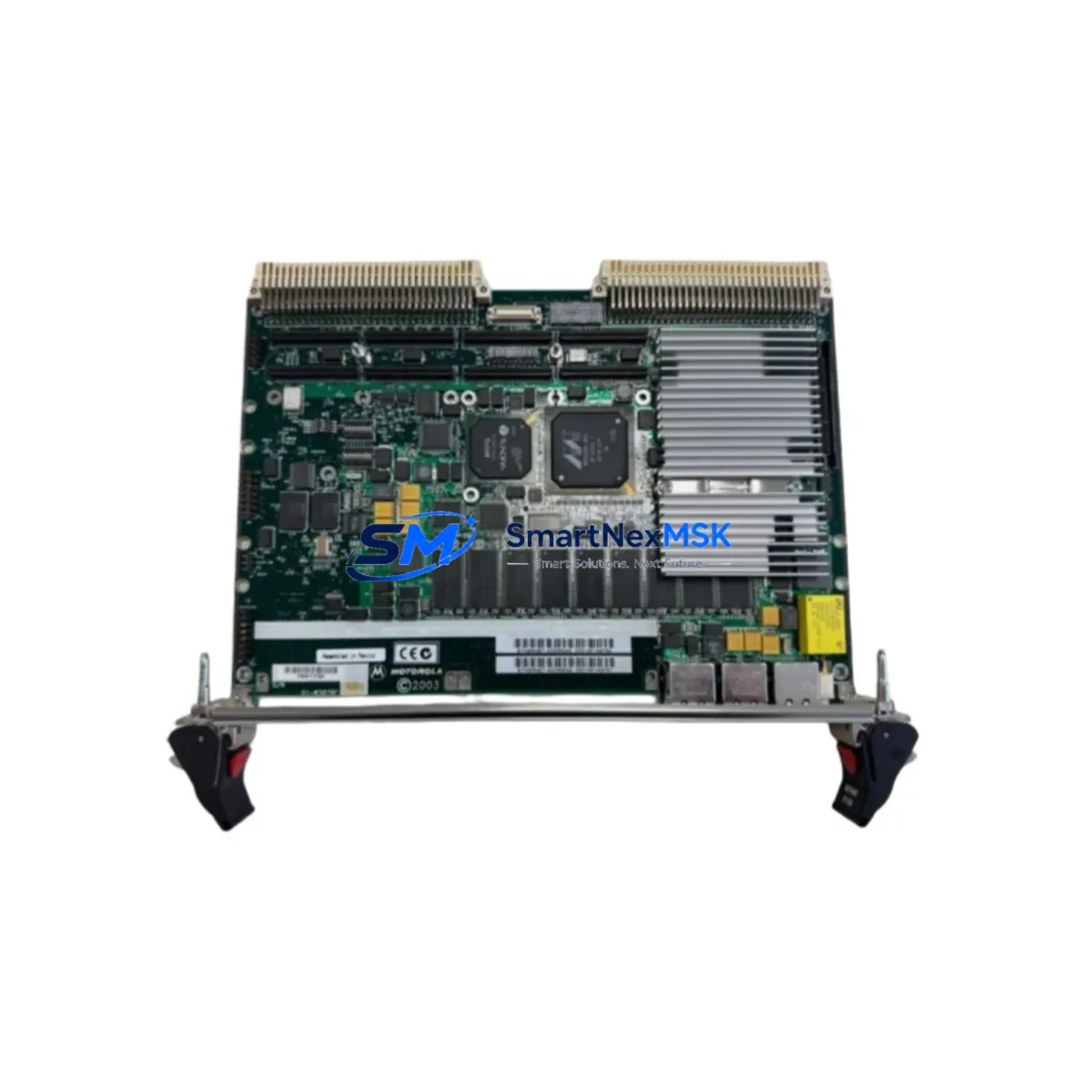
The VEM MVME6100 CPU4 SPS-A-098744 is a 6U VMEbus PowerPC single-board computer (SBC) designed for mission-critical industrial automation, process control, and legacy DCS/SCADA environments. As a maintenance-ready original spare, this unit is sourced, inspected, and tested to support rapid field replacement and minimize unplanned downtime in production facilities, power plants, and manufacturing lines that depend on MVME6100 Series VMEbus infrastructure.
For maintenance engineers managing aging VMEbus control systems, securing a verified spare of the MVME6100 CPU4 SPS-A-098744 is a proactive step in any planned maintenance or emergency recovery strategy. This board serves as the central processing unit within the VMEbus backplane, coordinating I/O, communications, and real-time control tasks. Its failure directly impacts system availability, making it one of the highest-priority components in any spare parts inventory for MVME6100-based control cabinets.
Spare Maintenance Table
| Parameter | Specification / Detail |
|---|---|
| Part Number / SKU | MVME6100 CPU4 SPS-A-098744 |
| Brand / Manufacturer | VEM |
| Series | MVME6100 Series |
| Form Factor | 6U VMEbus Single-Board Computer (SBC) |
| Processor Architecture | PowerPC (MPC7457 / Freescale) |
| Bus Standard | VMEbus (VME64 / VME64x compatible) |
| Product Type | VMEbus Single-Board Computer |
| Origin | Germany (DE) |
| Compatibility | MVME6100 Series VMEbus backplanes; compatible with standard 6U VME64 chassis |
| Typical Application | DCS/SCADA CPU replacement, process control, legacy automation system maintenance |
| Installation Environment | Industrial control cabinet, EMC-shielded enclosure, 0–55°C operating range (typical) |
| Maintenance Recommendation | Inspect backplane connectors, power rails, and cooling airflow before installation; verify firmware revision compatibility |
| Condition | Original spare — inspected and function-tested prior to shipment |
| Warranty | 12 Months |
| Shipping | Worldwide; ESD-safe anti-static packaging; tracked express available |
Maintenance Planning for Continuous Operation
When replacing the MVME6100 CPU4 SPS-A-098744 in a live control cabinet, a thorough inspection of the surrounding system is essential to prevent repeat failures and ensure stable resumption of operations. Maintenance engineers should treat this replacement as an opportunity for a broader cabinet health check.
Begin by verifying the VMEbus backplane itself — inspect connector pins for oxidation, mechanical damage, or intermittent contact, as a degraded backplane can cause the new CPU board to exhibit erratic behavior. Check the VMEbus power supply module (typically a dedicated +5V / ±12V industrial PSU) for output voltage stability and ripple; an aging or undersized power supply is a common root cause of SBC failures in long-running systems.
Inspect all I/O modules seated in the same VMEbus chassis — analog input/output cards, digital I/O boards, and counter/timer modules should be checked for firmware compatibility with the replacement CPU revision. Review the communication modules in the rack, including Ethernet, serial (RS-232/RS-485), and fieldbus interface cards (PROFIBUS, CANbus, or MIL-STD-1553 depending on the application), as these may require re-initialization after a CPU swap.
For systems with HMI panels connected via serial or Ethernet to the MVME6100 CPU, verify that the HMI communication parameters (baud rate, IP address, protocol settings) are correctly restored after the replacement. If the system uses signal isolators or signal conditioners between field sensors and the VMEbus I/O cards, inspect these for drift or degradation — they are often overlooked during CPU-focused maintenance events.
Check all terminal blocks and wiring harnesses connected to I/O modules in the cabinet. Loose terminations, corroded contacts, or undersized conductors can introduce noise that manifests as intermittent faults after a CPU replacement. Inspect fuse holders and circuit protection for the CPU power rail and I/O supply rails — replace any fuses showing signs of thermal stress. If the system includes a real-time clock (RTC) battery on the SBC or a separate battery-backed SRAM module, this is an ideal time to replace it to prevent time-sync and data-retention issues.
Finally, if the control system includes a watchdog timer module or an external system health monitor, verify that these are correctly configured to recognize the replacement CPU’s heartbeat signal before returning the system to automatic operation.
Site Replacement Workflow
Step 1 — Pre-replacement preparation: Document the current system configuration, firmware version, and any custom BIOS/boot settings stored on the existing MVME6100 CPU4 SPS-A-098744. Back up all configuration files to a portable storage device or engineering workstation.
Step 2 — Safe shutdown: Follow your site’s lockout/tagout (LOTO) procedure. Power down the VMEbus chassis in the correct sequence — disable field outputs before removing CPU power to prevent uncontrolled actuator states.
Step 3 — Board extraction: Use the VMEbus ejector handles to disengage the board from the backplane. Avoid flexing the board; use ESD wrist strap and mat throughout handling.
Step 4 — Compatibility verification: Confirm that the replacement MVME6100 CPU4 SPS-A-098744 matches the required hardware revision and firmware version. Check jumper settings and DIP switch configurations against the original board’s documentation or site records.
Step 5 — Installation and power-up: Seat the replacement board firmly into the VMEbus slot. Apply power in the correct sequence and monitor boot diagnostics via the front-panel serial console port. Verify that all I/O modules are recognized and that communication links are re-established.
Step 6 — Functional test: Run a full I/O scan and communication test before returning the system to automatic control. Confirm HMI displays are updating correctly and that no fault codes are active.
Step 7 — Documentation: Record the replacement date, new board serial number, firmware version, and any configuration changes in the site maintenance log. Update the spare parts inventory to reflect the consumed unit and initiate a replenishment order to maintain buffer stock.
This workflow is designed to minimize mean time to repair (MTTR) and reduce the risk of secondary failures during the recovery process. For older MVME6100-based systems approaching end-of-life, consider maintaining at least one additional spare CPU board to support long-term system continuity without dependency on spot-market availability.
Spare Parts Support FAQ
Q1: Is the MVME6100 CPU4 SPS-A-098744 a direct drop-in replacement for all MVME6100 Series variants?
The MVME6100 CPU4 SPS-A-098744 is designed for the MVME6100 Series VMEbus platform. Compatibility depends on the specific hardware revision and firmware version required by your system. We recommend providing your existing board’s revision markings and system documentation so our technical team can confirm compatibility before shipment. All units are function-tested prior to dispatch.
Q2: What is included in the 12-month warranty and how does it apply to field replacements?
Every MVME6100 CPU4 SPS-A-098744 supplied by SMARTNEXMSK carries a 12-month warranty covering manufacturing defects and functional failures under normal operating conditions. The warranty period begins from the date of shipment. In the event of a warranty claim, we provide a replacement unit or repair service with priority handling to minimize your system downtime.
Q3: How should this spare be stored if not immediately installed?
Store the MVME6100 CPU4 SPS-A-098744 in its original ESD-safe anti-static bag inside a dry, temperature-controlled environment (recommended: 10–30°C, relative humidity below 60%, away from direct sunlight and magnetic fields). Inspect the board annually if held in long-term storage, and verify the RTC battery condition before installation after extended storage periods.
Q4: Can SMARTNEXMSK support ongoing spare parts supply for MVME6100 Series systems?
Yes. SMARTNEXMSK maintains long-term sourcing relationships for MVME6100 Series components and related VMEbus spare parts. We support planned maintenance programs, emergency procurement, and consignment stock arrangements for facilities managing multiple VMEbus-based control systems. Contact our team to discuss a tailored spare parts support agreement for your site.
© 2026 SMARTNEXMSK. All rights reserved.
Original Source: https://smartnexmsk.com
Contact: sales@smartnexmsk.com | +86 18259474341