VIBRO-METER 244-127-000-017 A2-B02 Retrofit-Ready Galvanic Isolation Module for VM Series Control Systems
The VIBRO-METER 244-127-000-017 A2-B02 is a galvanic isolation module engineered for the VM Series condition monitoring and machinery protection platform. As legacy VM Series installations approach end-of-service milestones, this module serves as a verified retrofit-ready replacement for discontinued or aging signal conditioning components within existing control cabinets. Whether you are upgrading a turbine protection rack, replacing a failed isolation barrier in a compressor monitoring loop, or migrating from an older VIBRO-METER 200 Series chassis to a modernized VM600 architecture, the 244-127-000-017 A2-B02 provides the electrical isolation, signal fidelity, and form-factor compatibility required for a smooth transition with minimal downtime.
This module is designed to interface directly with VIBRO-METER VM600 racks and compatible backplane assemblies, maintaining galvanic separation between field-side sensor inputs and the control-side signal chain. It supports standard 4–20 mA and voltage signal formats commonly used in vibration, displacement, and process variable monitoring loops. When replacing an in-service unit, engineers should verify the backplane slot assignment, confirm the module address configuration matches the existing rack map, and validate that the replacement unit’s firmware revision is compatible with the host rack controller before energizing the loop.
During retrofit planning, it is essential to document the existing terminal wiring layout before removal. The 244-127-000-017 A2-B02 uses a standard VIBRO-METER terminal block format, but field wiring polarity, shield grounding points, and cable routing must be confirmed against the original loop drawing. In systems where the VM600 MPC4 or IOC4T I/O cards are installed in the same rack, the isolation module’s channel assignment must be cross-referenced with the rack’s I/O map to avoid address conflicts that could cause false alarms or missed trips in the machinery protection logic.
Upgrade Compatibility Table
| Parameter | Details |
|---|---|
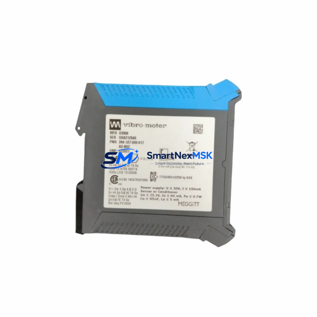
| SKU / Part Number | 244-127-000-017 A2-B02 |
| Brand | VIBRO-METER (Meggitt) |
| Compatible Platform | VM Series (VM600, VM200 retrofit path) |
| Module Function | Galvanic Isolation — signal conditioning between field sensors and control rack |
| Backplane Interface | VM600 rack backplane; verify slot type before installation |
| Signal Compatibility | 4–20 mA, voltage inputs; vibration, displacement, process variable loops |
| Installation Requirement | Confirm module address, terminal wiring polarity, and shield grounding |
| Communication Compatibility | Compatible with VM600 rack communication protocols; verify with host controller |
| Replacement Recommendation | Direct replacement for discontinued VM Series isolation modules; cross-check A2-B02 revision |
| Commissioning Focus | Loop calibration, alarm setpoint verification, trip relay function test |
| Warranty | 12-Month Warranty — covers manufacturing defects and functional failure under normal operating conditions |
| Origin | Switzerland (CH) |
Retrofit Planning for Existing Automation Systems
A successful retrofit of the 244-127-000-017 A2-B02 into an existing VM Series installation requires a structured approach that accounts for the interdependencies between the isolation module and the surrounding rack components. In a typical VM600 rack assembly, the galvanic isolation module operates alongside the VM600 MPC4 machinery protection card, which handles trip logic and relay output. The IOC4T I/O card manages the channel-to-system interface, while the RPS600 rack power supply provides the regulated DC bus that powers all installed modules. Before removing the existing isolation module, confirm that the RPS600 power supply output is within specification, as an under-voltage condition can cause erratic behavior during module hot-swap or cold-restart sequences.
Terminal wiring for the 244-127-000-017 A2-B02 follows the standard VIBRO-METER field terminal block layout. In installations where the original module has been in service for more than five years, terminal screws should be inspected for corrosion and re-torqued to specification after reconnection. Cable shields should be grounded at a single point — typically at the rack end — to prevent ground loops that can introduce noise into the vibration signal chain. In systems using VIBRO-METER CM3 or CM6 signal conditioning modules in adjacent slots, ensure that the new isolation module does not share a ground reference with these units unless the rack design explicitly supports it.
For facilities migrating from older VIBRO-METER 200 Series racks to the VM600 platform, the 244-127-000-017 A2-B02 is a key component in the signal path modernization. The migration typically involves replacing the legacy 200 Series backplane with a VM600 rack chassis, remapping I/O channel assignments in the host DCS or PLC, and updating HMI faceplates to reflect the new tag names and engineering unit scaling. In Modbus RTU or PROFIBUS DP communication environments, the VM600 rack’s communication card — such as the XMV16D or the AMC8 — must be reconfigured to match the updated channel map before the isolation module is brought online. Failure to synchronize the communication configuration with the physical rack layout can result in incorrect process variable readings at the DCS historian or SCADA display.
In control cabinets where space is constrained, the slim form factor of the 244-127-000-017 A2-B02 allows it to be installed without modification to the existing rack mounting hardware. However, if the cabinet also houses a VIBRO-METER VC-3200 or VC-3300 vibration controller, verify that the isolation module’s output signal range is compatible with the controller’s input specification before finalizing the wiring. Programming cable access for the VM600 rack — typically via the USB or RS-232 port on the rack controller — should be confirmed prior to the maintenance window to allow rapid firmware verification and channel configuration upload during commissioning.
Downtime Control During System Migration
Minimizing unplanned downtime during a galvanic isolation module replacement requires pre-staging the replacement unit, verifying its configuration offline, and coordinating the swap with the plant’s maintenance schedule. Before the maintenance window opens, the 244-127-000-017 A2-B02 should be bench-tested using a VIBRO-METER-compatible signal simulator to confirm that the module responds correctly to the expected input range and that its output signal is within the calibrated tolerance band. This pre-commissioning step reduces the risk of discovering a configuration mismatch after the old module has been removed from the live rack.
During the swap, the existing program logic in the VM600 rack controller should be exported and saved before any hardware changes are made. If the rack controller stores channel configuration parameters — such as alarm thresholds, trip setpoints, and filter settings — these values must be documented and re-entered after the new module is installed, as some firmware versions do not retain channel-specific parameters across a module replacement cycle. In facilities where the VM600 rack is integrated with a Rockwell Automation ControlLogix or Siemens S7-300 PLC via a hardwired relay interface, the PLC program’s input logic should be placed in a safe state before the isolation module is removed to prevent spurious trip signals from propagating to the process control layer.
After installation, the commissioning sequence should include a full loop check from the field sensor through the isolation module to the rack controller output, verification of alarm and trip relay operation, and confirmation that the DCS or SCADA system is receiving the correct process variable value. HMI screens that display vibration or displacement trends should be checked to ensure that the engineering unit scaling and tag mapping are consistent with the new module’s output. A final function test of the trip relay — using a test input signal that exceeds the configured trip setpoint — confirms that the protection logic is intact and that the system is ready to return to service.
Retrofit Support FAQ
Q1: Is the 244-127-000-017 A2-B02 a direct drop-in replacement for the original VM Series isolation module?
The 244-127-000-017 A2-B02 is designed as a retrofit-compatible replacement for VM Series galvanic isolation modules with the same backplane slot type and signal format. Before installation, verify the revision suffix (A2-B02) matches the rack’s hardware compatibility list, as earlier or later revisions may have different firmware requirements or terminal block configurations.
Q2: What wiring checks are required before installing the replacement module?
Confirm terminal polarity, cable shield grounding point, and field wiring continuity before inserting the new module. Re-torque all terminal screws to the manufacturer’s specified value. In multi-channel racks, verify that the channel address assignment on the new module matches the slot position in the rack’s I/O map to prevent channel cross-mapping errors.
Q3: How is communication compatibility verified after module replacement?
After installation, use the VM600 rack’s configuration software to read back the channel parameters and confirm that the module is recognized by the rack controller. In Modbus or PROFIBUS environments, verify that the process variable register address for the replaced channel is returning a valid value at the DCS or SCADA level. If the rack uses an XMV16D or AMC8 communication card, a communication diagnostic scan should be performed to confirm that all channels are reporting correctly.
Q4: What does the 12-month warranty cover, and what is the shipping lead time?
The 12-month warranty covers manufacturing defects and functional failure under normal operating conditions from the date of shipment. It does not cover damage resulting from incorrect installation, overvoltage, or environmental conditions outside the module’s rated specification. Units are shipped from verified stock with pre-shipment functional testing. Lead time varies by destination; contact the sales team for current availability and expedited shipping options.
© 2026 SMARTNEXMSK. All rights reserved.
Original Source: https://smartnexmsk.com
Contact: sales@smartnexmsk.com | +86 18259474341