VIBRO-METER PLD772 254-774-010-024 Maintenance-Ready Spare for CM Series Automation
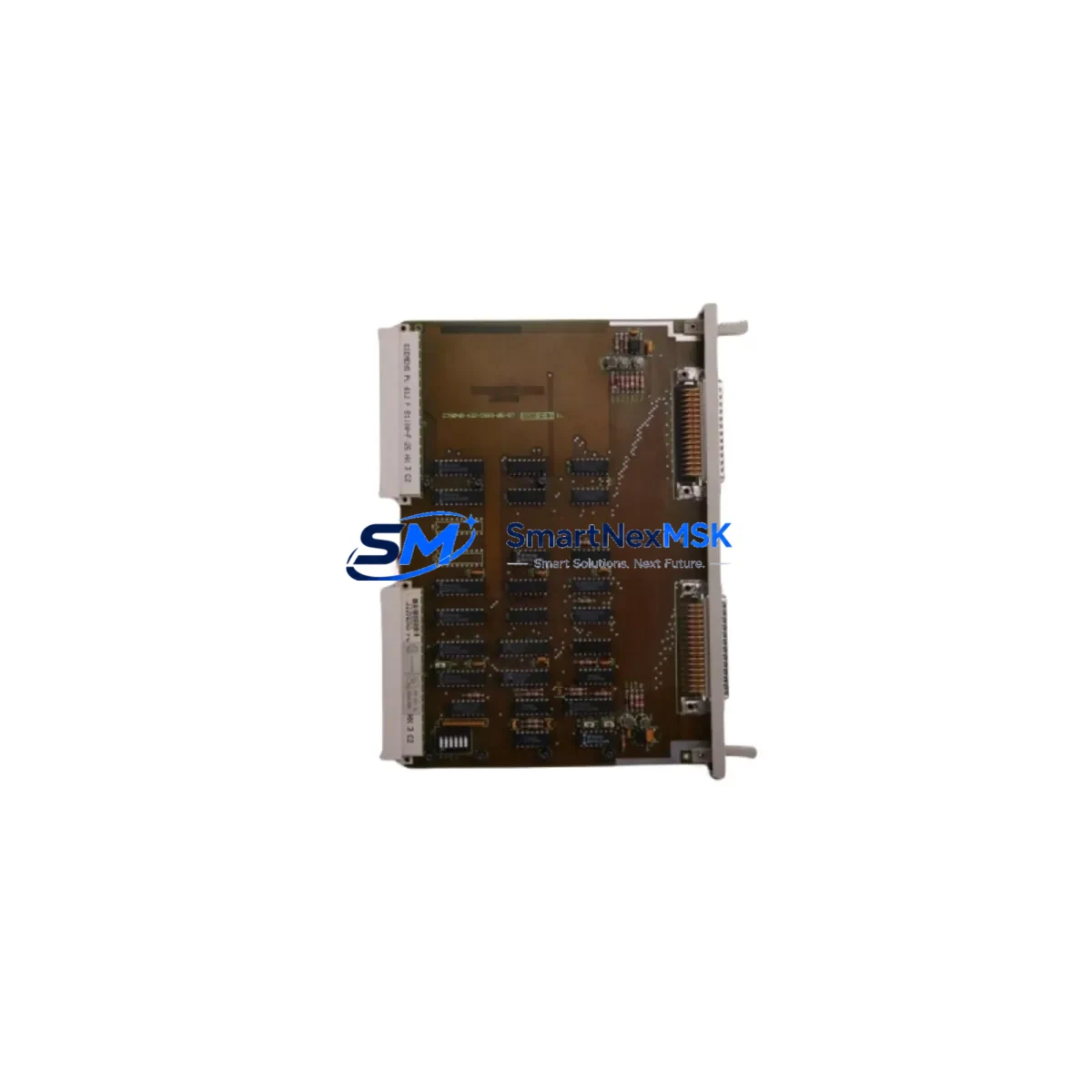
The VIBRO-METER PLD772 (P/N 254-774-010-024) is a precision vibration signal processor module designed for continuous operation in CM Series condition monitoring systems. As a maintenance-ready original spare, it supports rapid field replacement in rotating machinery protection applications — including turbines, compressors, pumps, and generators — where unplanned downtime carries significant operational and financial risk. Sourced directly from verified supply channels, each unit is inspected and function-tested prior to shipment, backed by a 12-month warranty.
For maintenance engineers managing aging CM Series installations, the PLD772 represents a critical line-of-defense component. Its role in signal conditioning and vibration channel processing means that a failed or degraded module can blind the entire protection loop, masking dangerous machinery faults. Keeping a qualified spare on the shelf — or sourcing one with a guaranteed lead time — is a fundamental element of any serious predictive maintenance or reliability-centered maintenance (RCM) program.
Spare Maintenance Table
| Parameter | Specification / Detail |
|---|---|
| Part Number | PLD772 / 254-774-010-024 |
| Brand | VIBRO-METER (Meggitt) |
| Series | CM Series (Condition Monitoring) |
| Module Type | Vibration Signal Processor / Channel Card |
| Application | Rotating machinery protection: turbines, compressors, pumps, fans |
| Signal Input | Compatible with VIBRO-METER piezoelectric and eddy-current transducers |
| Installation | Rack-mount, CM Series backplane slot — direct drop-in replacement |
| Origin | Switzerland |
| Compatibility | CM Series racks; verify slot assignment and firmware revision before installation |
| Condition | Original spare; function-tested before shipment |
| Warranty | 12 Months |
| Typical Lead Time | In stock — ships within 2–5 business days |
| Maintenance Recommendation | Replace at first sign of channel fault, signal drift, or alarm inhibit; inspect backplane connector pins during swap |
Maintenance Planning for Continuous Operation
When a PLD772 channel card is flagged for replacement during a scheduled outage or emergency callout, experienced maintenance engineers treat the event as a trigger for a broader cabinet inspection. The CM Series rack is a tightly integrated system, and a single module failure often reflects stress on adjacent components that share the same power rail, backplane, or signal loop.
Start by verifying the CM Series rack power supply module — typically a dedicated 24 VDC or dual-redundant supply — since voltage ripple or transient spikes are a leading cause of premature processor card failure. If the power supply shows any sign of output instability, it should be replaced concurrently with the PLD772 to prevent repeat failures. Next, inspect the CM Series backplane for oxidized or damaged connector pins at the affected slot; a corroded backplane contact can cause intermittent channel faults that mimic a failed processor card.
The signal input wiring and transducer cables connected to the PLD772 channel deserve close attention. Shielded cables from piezoelectric accelerometers or eddy-current proximity probes should be checked for insulation damage, shield continuity, and correct termination. A compromised cable can inject noise that degrades the replacement module’s performance from day one. If the installation uses VIBRO-METER signal conditioners or in-line isolators between the transducer and the rack, verify their output levels and isolation integrity as part of the same work order.
For systems with relay output cards — such as the CM Series relay output modules used for alarm and trip functions — confirm that the relay contacts associated with the replaced channel are operating correctly after the PLD772 swap. A stuck or welded relay contact can prevent the protection system from responding to a genuine machinery fault even after the processor card is restored. Similarly, if the CM rack communicates with a plant DCS or SCADA via a CM Series communication gateway or Modbus interface card, verify that the channel data is correctly mapped and transmitted after the replacement.
In installations where the CM Series system feeds a plant historian or condition monitoring software platform, re-validate the channel tag assignment and engineering unit scaling after the PLD772 is installed. Mismatched scaling can produce false trend data that undermines long-term predictive maintenance decisions. Finally, if the site uses a portable vibration analyzer or handheld calibrator for post-maintenance verification, perform a functional check on the replaced channel before returning the machine to service — confirming that alarm setpoints, danger thresholds, and OK relay status all respond correctly.
Site Replacement Workflow
Step 1 — Preparation: Obtain the CM Series rack drawing and channel assignment list. Confirm the PLD772 slot number, firmware version compatibility, and any jumper or DIP switch settings required for the specific channel configuration. Cross-reference the replacement unit’s part number (254-774-010-024) against the installed unit label before proceeding.
Step 2 — Safe Isolation: Follow site lock-out/tag-out (LOTO) procedures. For hot-swap capable CM Series racks, confirm whether the slot supports live replacement; if not, coordinate a controlled shutdown window with operations to minimize production impact.
Step 3 — Module Swap: Remove the failed PLD772 by releasing the front-panel ejector levers. Inspect the backplane connector and slot guides before inserting the replacement. Seat the new module firmly and verify the front-panel status LED sequence on power-up.
Step 4 — Functional Verification: Using the CM Series configuration software or a portable calibrator, inject a known reference signal and confirm that the channel output, alarm relay, and communication data all respond within specification. Document the as-found and as-left readings in the site maintenance management system (CMMS).
Step 5 — Return to Service: Remove LOTO, restore normal monitoring, and update the spare parts inventory record. Log the replaced module’s serial number and failure mode for reliability trend analysis. A properly executed PLD772 replacement — with concurrent inspection of the power supply, backplane, transducer cables, and relay outputs — typically restores full CM Series protection loop integrity within a single planned maintenance window, avoiding repeat callouts and unplanned shutdowns.
Spare Parts Support FAQ
Q1: Is the PLD772 254-774-010-024 a direct drop-in replacement for all CM Series racks?
The PLD772 is designed for CM Series rack installations, but slot compatibility depends on the specific rack model and firmware revision in use at your site. Before ordering, provide your rack model number and existing channel card part number for compatibility confirmation. Our technical team can cross-reference your configuration and advise on any jumper settings or firmware considerations required for a seamless swap.
Q2: What testing is performed before shipment?
Every PLD772 unit is function-tested prior to dispatch to verify basic electrical integrity and signal processing performance. Units are shipped with protective packaging suited for sensitive electronics. A 12-month warranty covers manufacturing defects and functional failures under normal operating conditions from the date of receipt.
Q3: How should we manage PLD772 inventory for a multi-unit CM Series installation?
For sites with four or more CM Series racks, maintaining at least one PLD772 spare per channel type on-site is recommended. Given the module’s role in machinery protection, a stockout during an emergency callout can extend unplanned downtime significantly. We offer long-term supply agreements and reserved stock arrangements for high-criticality sites to ensure availability without tying up excessive capital in on-site inventory.
Q4: What is the warranty and return policy if the module does not resolve the fault?
All units carry a 12-month warranty from the date of receipt. If the PLD772 does not resolve the reported fault after correct installation, our technical support team will assist with root-cause diagnosis — including review of backplane condition, power supply stability, and transducer signal integrity. Warranty claims are processed promptly, with replacement or credit issued upon confirmation of the defect.
© 2026 SMARTNEXMSK. All rights reserved.
Original Source: https://smartnexmsk.com
Contact: sales@smartnexmsk.com | +86 18259474341