X-RITE GM10032582-KIT Retrofit-Ready PC Board Assembly for GM Series Control Systems
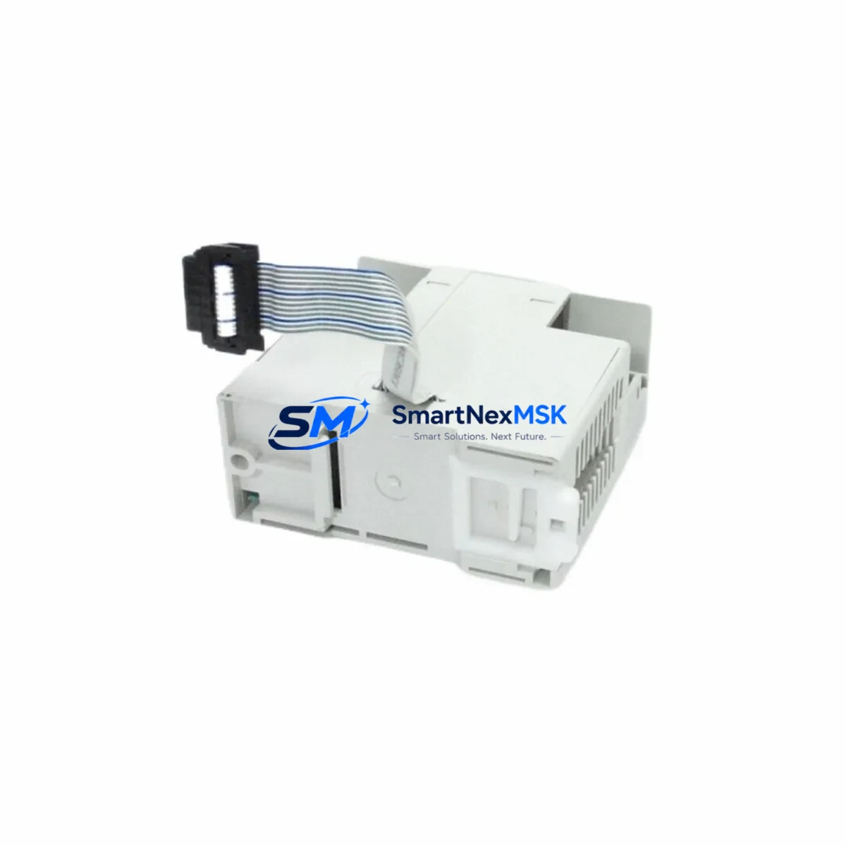
The X-RITE GM10032582-KIT is a retrofit-ready PC board assembly engineered as a direct replacement for legacy GM Series colorimetry and measurement instrument platforms. As X-RITE’s installed base of GM Series instruments ages into end-of-support cycles, facilities managers and instrumentation engineers face increasing pressure to source verified replacement boards that restore full operational capability without requiring a complete instrument overhaul. The GM10032582-KIT addresses this need precisely — delivering a factory-equivalent PCB assembly that slots into existing GM Series chassis with minimal re-engineering effort, protecting your capital investment and reducing unplanned downtime.
Whether you are replacing a failed board in a production-critical colorimeter, upgrading a degraded assembly in a quality-control station, or building a spare-parts inventory for a fleet of GM Series instruments, the GM10032582-KIT provides the component-level solution that keeps your measurement systems operational. Each unit is sourced from verified supply channels, inspected prior to dispatch, and covered by a 12-month warranty against manufacturing defects and functional failure.
Upgrade Compatibility Table
| Parameter | Details |
|---|---|
| Compatible Platform | X-RITE GM Series colorimetry instruments |
| Replacement Target | OEM PC Board Assembly (GM10032582-KIT) |
| Installation Interface | Direct board-level swap; existing chassis mounting points retained |
| Communication Compatibility | Compatible with existing GM Series internal bus and interface connectors |
| Connector / Terminal Compatibility | Matches OEM terminal layout; no rewiring required under standard retrofit |
| Firmware / Software | Verify instrument firmware version prior to installation; reflash may be required for older revisions |
| Calibration Requirement | Full instrument recalibration recommended post-installation per X-RITE service procedures |
| Retrofit Complexity | Moderate — ESD precautions required; recommend qualified instrumentation technician |
| Warranty | 12 months from date of shipment; covers manufacturing defects and functional failure |
| Lead Time | In-stock units ship within 3–5 business days; global shipping available |
Retrofit Planning for Existing Automation Systems
Successful integration of the GM10032582-KIT into an existing GM Series instrument requires systematic pre-installation planning. Before removing the failed board, document the current instrument configuration: record all calibration coefficients stored in the instrument memory, photograph the existing board’s connector positions and any jumper or DIP switch settings, and verify the instrument’s power supply rail voltages using a calibrated multimeter. The GM Series power supply module typically delivers regulated DC rails to the PCB; confirm these are within specification before installing the replacement board, as an out-of-tolerance power supply can damage a new assembly immediately upon power-up.
Terminal and connector verification is equally critical. The GM10032582-KIT uses the same connector footprint as the original OEM assembly, but technicians should inspect the mating connectors on the instrument harness for pin corrosion, bent contacts, or cracked housings — common failure modes in instruments that have operated in humid or chemically active environments. If the instrument is part of a larger quality-control automation cell, also verify the interface cable connecting the GM Series instrument to any upstream data acquisition system or SCADA host; cables carrying RS-232 or USB signals to a host PC running X-RITE’s measurement software should be tested for continuity and shielding integrity before the retrofit is declared complete.
For facilities running multiple GM Series units in a networked configuration — for example, instruments connected via a USB hub or serial multiplexer to a central measurement server — the board replacement on one unit should be treated as an isolated event. Disconnect the target instrument from the network before beginning work to prevent any bus contention or address conflicts during the power-cycle sequence. After installation, re-introduce the instrument to the network one step at a time, confirming that the host software recognizes the instrument at its expected device address before resuming automated measurement routines.
Technicians working on GM Series retrofits frequently encounter the need to simultaneously address adjacent components. Common co-replacement items in the same service event include the instrument’s illumination assembly, the detector array module, the optical filter wheel mechanism, the instrument’s internal power regulation board, and the external interface cable set. In some cases, the front-panel keypad membrane or display module may also require replacement if the original failure event involved a power surge. Having these components available as part of a planned retrofit kit — rather than sourcing them reactively after the board swap — significantly reduces total instrument downtime.
If the GM Series instrument feeds measurement data into a broader factory automation environment — for instance, triggering pass/fail signals to a downstream PLC-controlled sorting or rejection system — coordinate the retrofit window with the automation team to ensure the PLC logic is placed in a safe hold state during the instrument outage. This prevents false rejection events or missed quality gates during the period when the instrument is offline.
Downtime Control During System Migration
Minimizing instrument downtime during a GM10032582-KIT board replacement requires a structured approach that begins well before the physical swap. The most effective strategy is to pre-stage all required materials — replacement board, ESD mat and wrist strap, calibration tile set, firmware update files if applicable, and the instrument’s service manual — so that the actual hands-on replacement window is as short as possible. In production environments where the GM Series instrument is part of a continuous quality-control loop, schedule the replacement during a planned maintenance window or shift changeover to avoid disrupting active measurement campaigns.
Before powering down the instrument, export or record all stored calibration data and measurement profiles. X-RITE GM Series instruments store calibration coefficients internally; if the replacement board does not retain these values (which is typical for a full board swap), the instrument will require a complete recalibration sequence using the appropriate calibration tile or standard reference before it can return to service. Pre-positioning the calibration standards at the instrument location before beginning the swap eliminates the delay of locating them after the board is installed.
After installing the GM10032582-KIT, perform a systematic power-on verification: confirm that the instrument initializes without error codes, that all status indicators are nominal, and that the instrument responds correctly to the host software’s device query. Run a full calibration cycle and verify measurement results against a known reference standard before releasing the instrument back to production. Document the calibration results and the date of board replacement in the instrument’s maintenance log. This record supports both internal quality-system requirements and any future warranty claims under the 12-month coverage period.
For facilities that cannot tolerate any measurement gap, consider maintaining a pre-calibrated spare GM Series instrument that can be swapped into the measurement station while the primary unit undergoes board replacement. This hot-swap approach keeps the quality-control process running continuously and allows the board replacement and recalibration to be completed without time pressure.
Retrofit Support FAQ
Q1: Is the GM10032582-KIT a direct drop-in replacement for the original X-RITE GM Series PC board assembly?
A: Yes, the GM10032582-KIT is designed as a direct board-level replacement for the original OEM assembly used in GM Series instruments. The connector layout, mounting hole pattern, and electrical interface are equivalent to the original. However, we recommend verifying your specific instrument revision against the board part number before installation, as minor hardware revisions within the GM Series may affect compatibility. Contact our technical team with your instrument serial number for confirmation.
Q2: What commissioning steps are required after installing the replacement board?
A: After installation, power on the instrument and confirm it initializes without fault codes. Perform a full calibration sequence using the appropriate X-RITE calibration tile or reference standard for your GM Series model. If the instrument is connected to a host PC running X-RITE measurement software, verify that the software recognizes the instrument and that measurement results are within expected tolerance before returning the instrument to production service. Firmware verification and update (if required) should be completed before calibration.
Q3: How do I verify wiring and connector compatibility before installation?
A: Inspect all mating connectors on the instrument harness for pin corrosion, bent contacts, and housing cracks before installing the new board. Verify that the instrument’s internal power supply rails are within specification using a calibrated multimeter. Photograph the original board’s connector and jumper configuration before removal so you can replicate the setup on the replacement board. If any harness connectors show signs of damage, replace them before installing the GM10032582-KIT to avoid damaging the new assembly.
Q4: What does the 12-month warranty cover, and how is a claim initiated?
A: The 12-month warranty covers manufacturing defects and functional failure of the GM10032582-KIT board assembly under normal operating conditions. It does not cover damage resulting from incorrect installation, overvoltage events, ESD damage, or physical mishandling. To initiate a warranty claim, contact our sales team with your order reference, instrument serial number, a description of the failure symptom, and any relevant error codes or photographs. We will arrange for inspection and, where the claim is validated, replacement or repair at no additional cost.
© 2026 SMARTNEXMSK. All rights reserved.
Original Source: https://smartnexmsk.com
Contact: sales@smartnexmsk.com | +86 18259474341