XINJE XC3-60R-E Retrofit-Ready Relay PLC for XC3 Series: Compatible Modernization & Smooth Legacy System Upgrade
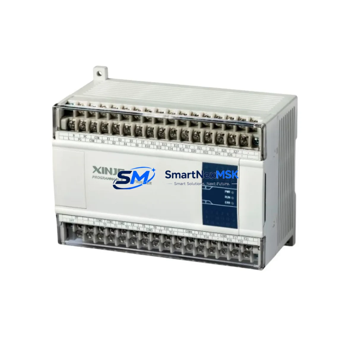
The XINJE XC3-60R-E is a 60-point relay output programmable logic controller designed for industrial automation environments where legacy system continuity, backward compatibility, and minimal retrofit risk are paramount. With 36 digital inputs and 24 relay outputs, AC power supply, and dual serial communication ports (RS232 and RS485), this module is engineered as a direct functional replacement for discontinued or aging XC3 Series controllers deployed across manufacturing lines, process control cabinets, and machine tool applications throughout China and Southeast Asia.
For engineers managing aging automation infrastructure, the XC3-60R-E delivers a proven migration path. Whether you are replacing a failed unit, upgrading a control cabinet to extend service life, or consolidating I/O capacity across a multi-rack system, this controller maintains full compatibility with existing XC3 Series ladder logic programs developed in XINJE’s XCPPro programming environment. Program files compiled for earlier XC3 variants can typically be downloaded to the XC3-60R-E without structural modification, significantly reducing re-commissioning time and the risk of logic errors during cutover.
Upgrade Compatibility Table
| Parameter | Details |
|---|---|
| Model | XINJE XC3-60R-E |
| I/O Points | 36 DI / 24 DO (Relay) |
| Power Supply | AC 85–264V |
| Communication Ports | COM1: RS232 / COM2: RS485 |
| Programming Software | XCPPro (compatible with XC3 Series projects) |
| Backplane / Rack | Standalone; no expansion backplane required for base I/O |
| Replaces / Compatible With | XC3-48R-E, XC3-48T-E, XC3-60T-E and other XC3 Series variants |
| Communication Compatibility | Modbus RTU (Master/Slave), XinJEBus, free-port protocol |
| Installation | DIN rail mount; standard 35mm rail |
| Retrofit Recommendation | Verify terminal pitch and wiring gauge before cutover |
| Commissioning Focus | Module address assignment, COM port baud rate, HMI tag mapping |
| Warranty | 12 Months from date of shipment |
Retrofit Planning for Existing Automation Systems
Successful retrofit of the XC3-60R-E into an existing control cabinet begins well before the physical swap. Engineers should first audit the power supply capacity of the existing panel — the XC3-60R-E draws from an AC source, and the cabinet’s 24VDC rail (typically supplied by a XINJE XP series or equivalent switching power supply) must be verified to support any connected sensor loads independently. If the legacy system used a DC-powered XC3 variant such as the XC3-48T-E with transistor outputs, note that the XC3-60R-E uses relay outputs, which affects switching frequency and inductive load handling; relay contacts are rated for resistive loads and require suppression circuits (RC snubbers or flyback diodes) on inductive outputs such as solenoid valves and motor contactors.
Terminal wiring compatibility is the next critical checkpoint. The XC3-60R-E uses the same terminal block pitch as other XC3 Series units, but engineers should confirm wire ferrule sizing and terminal torque specifications before reusing existing field wiring harnesses. In retrofit scenarios where the original unit was mounted alongside an XC-E16X or XC-E16YR expansion module for additional I/O, the expansion bus connector and module address DIP switch settings must be re-verified after installation, as address conflicts can cause silent I/O failures that are difficult to diagnose under live conditions.
For systems communicating over RS485 Modbus RTU — common in applications linking the PLC to a XINJE TH series HMI, a variable frequency drive (VFD), or a remote I/O station — the COM2 port baud rate, parity, and station address must match the legacy configuration exactly. If the original system used a XINJE XC-MODEM or third-party RS485-to-Ethernet gateway for SCADA connectivity, the gateway’s polling parameters should be documented before the swap and restored immediately after. HMI screen projects developed in XINJE TouchWin or TP series panels typically reference PLC register addresses directly; confirm that the register map of the XC3-60R-E matches the original unit to avoid HMI display errors or write failures after cutover.
Where the legacy system included a XINJE XC series programming cable (USB-SC09 or RS232 direct) for on-site program maintenance, ensure the replacement cable is available on-site during commissioning. Program backup from the original unit — if still functional — should be completed before removal and stored as a reference baseline. If the original unit has already failed and no program backup exists, reconstruction from electrical drawings and HMI tag lists is required; the XC3-60R-E’s instruction set is fully compatible with XCPPro, and standard function blocks for PID loops, high-speed counters, and communication instructions are supported natively.
Downtime Control During System Migration
Minimizing production downtime during a PLC cutover requires a structured pre-outage preparation phase. Before the scheduled maintenance window, complete all of the following: download and verify the program backup from the original XC3 unit; document all COM port settings, I/O force tables, and retentive data register values; photograph or sketch the existing terminal wiring layout; and confirm that the replacement XC3-60R-E has been bench-tested with the program loaded and I/O verified against a test rig or simulator.
During the cutover window, follow a sequential process: isolate the control cabinet from field power, remove the original unit, install the XC3-60R-E on the DIN rail, reconnect field wiring terminal by terminal using the documented layout, restore COM port parameters, and download the verified program. Before returning the system to automatic mode, perform a manual I/O scan to confirm all digital inputs read correctly and all relay outputs actuate the correct field devices. For systems with safety interlocks or emergency stop circuits, verify E-stop logic independently before enabling automatic operation.
Retentive data registers (D registers marked as retentive in the original program) should be restored from the backup data file if the application requires continuity of counters, setpoints, or recipe parameters. The XC3-60R-E supports retentive memory configuration through XCPPro, and this step is frequently overlooked during rushed cutovers, leading to process upsets on first restart. Planned cutovers with a 2–4 hour maintenance window are typically sufficient for a like-for-like XC3 Series replacement when preparation is complete.
Retrofit Support FAQ
Q1: Is the XC3-60R-E a direct drop-in replacement for the XC3-48R-E or XC3-60T-E?
The XC3-60R-E is functionally compatible with other XC3 Series controllers and accepts the same XCPPro program files. However, it is not pin-for-pin identical to transistor output variants (XC3-60T-E). Relay output wiring and load ratings differ from transistor outputs. Verify your field device wiring and output load specifications before substituting a transistor-output model with a relay-output model.
Q2: Can I reuse my existing HMI project and SCADA tags after replacing the PLC?
Yes, provided the replacement XC3-60R-E uses the same register address map as the original unit. XINJE TH/TP series HMI projects and Modbus-based SCADA systems reference D, M, Y, and X register addresses directly. If the original program is loaded unchanged onto the XC3-60R-E, all register addresses remain valid and HMI communication should resume without tag remapping.
Q3: What pre-shipment testing is performed on the XC3-60R-E?
Each unit undergoes functional verification including power-on self-test, I/O point actuation check, and communication port loopback test before shipment. Units are shipped with factory default settings; customer programs must be downloaded on-site. A 12-month warranty covers manufacturing defects from the date of shipment.
Q4: What should I check if the XC3-60R-E does not communicate with my HMI or VFD after installation?
First verify COM port assignment (COM1 vs COM2), baud rate, parity, stop bits, and station address match the legacy configuration. Check RS485 termination resistor settings if the bus is long or has multiple nodes. Confirm the HMI communication driver is set to the correct PLC type (XINJE XC Series). If using a USB-to-RS232 adapter for programming, ensure the correct COM port driver is installed on the engineering laptop.
© 2026 SMARTNEXMSK. All rights reserved.
Original Source: https://smartnexmsk.com
Contact: sales@smartnexmsk.com | +86 18259474341