XP Power F7E1A6G2 Maintenance-Ready Spare F7E Automation
Industrial automation systems depend on reliable power delivery, and the XP Power F7E1A6G2 is a cornerstone component in that chain. As a 700W AC-DC power supply module from XP Power’s F7E Series, the F7E1A6G2 is engineered for continuous-duty industrial environments — from process control panels and PLC enclosures to distributed I/O cabinets and motor drive systems. When this module fails or approaches end-of-life, every minute of unplanned downtime carries real operational cost. Maintaining a verified spare of the F7E1A6G2 in your parts inventory is one of the most effective strategies for protecting production continuity.
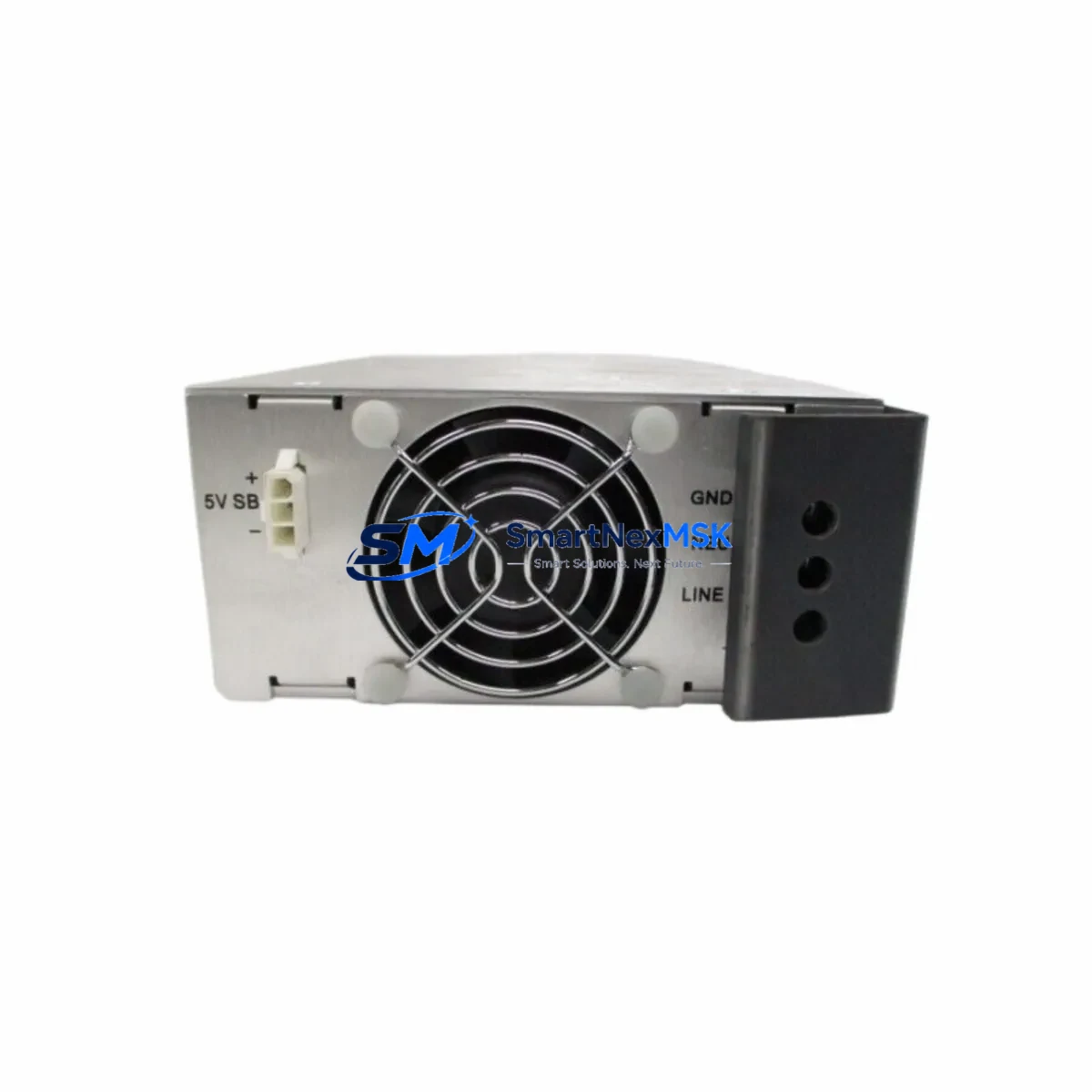
Maintenance engineers and procurement teams sourcing the F7E1A6G2 as a replacement spare should confirm several key parameters before installation. The module operates on a wide-range AC input (typically 85–264 VAC), making it compatible with both 110V and 230V site supplies without manual switching — a critical advantage in multi-site or international deployments. Output voltage and current ratings must be cross-checked against the load profile of the control cabinet, particularly if the original unit has been powering a mix of 24VDC logic circuits, relay coils, and field instruments simultaneously.
When replacing the F7E1A6G2 in an existing control cabinet, the maintenance workflow should extend beyond the power supply itself. Terminal block wiring — including input L/N/PE connections and DC output distribution terminals — must be inspected for signs of thermal stress, loose crimps, or insulation degradation that may have contributed to the original failure. If the cabinet also houses an XP Power F7E1A6G1 or F7E1A6G3 as a redundant or parallel supply, those units should be load-tested simultaneously to confirm balanced current sharing and proper OR-ing diode function.
In PLC-based control systems, the F7E1A6G2 typically powers the CPU rack, I/O modules, and communication interfaces. During a planned replacement, maintenance teams should verify that the 24VDC rail voltage remains within tolerance (±1%) under full load before reconnecting field devices. Systems using Siemens S7-300 or S7-400 racks, for example, may include PS307 or PS405 power supply modules that interact with the same DC bus — these should be checked for output ripple and voltage stability after the F7E1A6G2 is swapped. Similarly, if the cabinet includes a Phoenix Contact QUINT or TRIO power supply as a secondary source, its buffer capacitor status and alarm relay output should be verified post-replacement.
For DCS environments — such as those running Emerson DeltaV, Honeywell Experion, or ABB System 800xA — the F7E1A6G2 may supply power to marshalling cabinets, I/O termination assemblies, or fieldbus segment power conditioners. In these applications, signal isolation barriers, HART multiplexers, and Foundation Fieldbus power supplies sharing the same DC rail must be confirmed operational after the power module is replaced. Any interruption to the 24VDC supply in a HART or PROFIBUS PA segment can cause field device re-initialization, requiring loop checks and instrument re-ranging before the system returns to normal operation.
Procurement engineers should also consider the broader spare parts ecosystem when stocking the F7E1A6G2. Related components that frequently appear on the same bill of materials include DIN rail fuse holders (such as Weidmüller or Phoenix Contact types), miniature circuit breakers for input protection, 24VDC surge protection devices, and DC bus distribution blocks. Keeping these items alongside the F7E1A6G2 spare ensures that a complete cabinet restoration can be completed in a single maintenance window without waiting for secondary parts deliveries.
All F7E1A6G2 units supplied by SMARTNEXMSK are sourced from authorized channels, individually tested for output voltage accuracy, ripple, and thermal performance prior to shipment, and covered by a 12-month warranty. Fast global shipping from Xiamen stock ensures that emergency replacement orders can be fulfilled within 24–72 hours for most destinations.
Spare Maintenance Table
| Parameter | Specification / Detail |
|---|---|
| SKU | F7E1A6G2 |
| Brand / Series | XP Power / F7E Series |
| Product Type | AC-DC Power Supply Module |
| Output Power | 700W (nominal) |
| Input Voltage | 85–264 VAC, universal wide-range input |
| Output Voltage | 24 VDC (regulated) |
| Mounting | DIN rail / panel mount |
| Cooling | Convection / forced air (model-dependent) |
| Protection | OVP, OCP, OTP, short-circuit protection |
| Operating Temperature | -25°C to +70°C (derate above 50°C) |
| Compliance | CE, UL, RoHS |
| Origin | United Kingdom |
| Compatibility | Direct replacement for F7E Series installations; compatible with Siemens S7, DeltaV, ABB 800xA, PROFIBUS PA, HART systems |
| Installation | Verify terminal torque, DC output polarity, and load current before energizing |
| Commissioning Note | Measure output voltage under full load; confirm ripple <1% before reconnecting field devices |
| Warranty | 12-Month Warranty — tested before shipment |
Maintenance Planning for Continuous Operation
Effective maintenance planning for systems powered by the XP Power F7E1A6G2 requires a holistic view of the control cabinet’s electrical architecture. The power supply does not operate in isolation — it feeds a network of downstream components whose health directly affects system reliability.
During scheduled cabinet inspections, maintenance engineers should simultaneously check the condition of the 24VDC wiring harness, terminal block torque values, and DIN rail grounding continuity. Fuse holders protecting individual output branches — particularly Weidmüller or Phoenix Contact blade-type fuse terminals — should be inspected for contact resistance and replaced if discoloration or heat marks are present. Miniature circuit breakers (MCBs) on the AC input side should be exercised to confirm trip mechanism integrity.
In PLC cabinets, the F7E1A6G2 typically co-exists with CPU modules, digital I/O cards, analog input modules, and communication processors. When performing a power supply replacement, it is good practice to document the 24VDC rail voltage before and after the swap using a calibrated multimeter. If the cabinet includes a Siemens SITOP PSU8200 or a Murr Elektronik MCS power supply as a backup unit, its output should be verified independently. Signal isolators and loop-powered transmitter barriers sharing the DC bus should be checked for correct supply voltage after the F7E1A6G2 is reinstalled.
For systems with redundant power architectures, the OR-ing module or diode assembly connecting the F7E1A6G2 to its redundant partner should be tested for forward voltage drop and thermal performance. Surge protection devices (SPDs) on the DC output rail — such as Phoenix Contact TRABTECH or Dehn types — should be inspected for indicator status and replaced if the protection element has been triggered. Keeping a small stock of these ancillary components alongside the F7E1A6G2 spare significantly reduces the risk of extended downtime during emergency maintenance.
Site Replacement Workflow
Replacing the XP Power F7E1A6G2 on-site follows a structured sequence designed to minimize downtime and protect connected equipment:
- Step 1 — Isolation: Isolate the AC input supply using the cabinet’s main MCB or isolator switch. Confirm zero voltage on the AC input terminals using a calibrated voltage tester before proceeding.
- Step 2 — Documentation: Photograph or record the existing terminal wiring layout, including L, N, PE input connections and all DC output terminal assignments. Note any cable labels or ferrule markings for reference during reinstallation.
- Step 3 — Removal: Loosen terminal screws and disconnect all wiring. Release the DIN rail locking tab and slide the F7E1A6G2 free from the rail. Inspect the vacated rail section for debris or corrosion.
- Step 4 — Installation: Clip the replacement F7E1A6G2 onto the DIN rail and confirm it is fully seated. Reconnect all wiring per the documented layout, applying correct terminal torque (typically 0.5–0.8 Nm for 2.5mm² conductors).
- Step 5 — Pre-energization Check: Verify AC input wiring polarity and PE connection. Confirm no short circuits on the DC output rail using a continuity tester.
- Step 6 — Energization and Verification: Apply AC power and measure DC output voltage under no-load, then under full load. Confirm voltage is within ±1% of rated output. Check for abnormal heat, noise, or alarm indicators.
- Step 7 — System Restoration: Reconnect field devices and I/O modules sequentially. Verify PLC or DCS communication links are re-established. Perform a functional loop check on critical control loops before returning the system to automatic operation.
This workflow is applicable whether the F7E1A6G2 is being replaced as a planned maintenance action or as an emergency response to an unplanned failure. The structured approach ensures that no secondary faults are introduced during the replacement process and that the system is returned to full operational status with confidence.
Spare Parts Support FAQ
Q1: Is the F7E1A6G2 a direct drop-in replacement for the existing unit in my cabinet?
Yes. The F7E1A6G2 is a direct replacement for existing F7E Series installations. The DIN rail footprint, terminal layout, and electrical ratings are identical to the original specification. No wiring modifications or bracket adapters are required for standard F7E Series cabinet configurations.
Q2: How do I verify compatibility before ordering?
Cross-reference the SKU on the nameplate of your existing unit with F7E1A6G2. Confirm the output voltage (24VDC), output current rating, and input voltage range match your site supply. If your cabinet uses a different output voltage variant (e.g., 12V or 48V), contact sales@smartnexmsk.com with your nameplate data for confirmation before ordering.
Q3: What testing is performed before shipment?
Every F7E1A6G2 unit is individually tested for output voltage accuracy, load regulation, ripple and noise, and thermal performance under rated load conditions before dispatch. A test report is available upon request. All units are shipped with protective packaging to prevent transit damage.
Q4: What does the 12-month warranty cover?
The 12-month warranty covers manufacturing defects, component failures under normal operating conditions, and output performance deviations from rated specifications. Warranty claims are supported by SMARTNEXMSK’s technical team with replacement or repair options. The warranty period begins from the date of confirmed delivery. For warranty service, contact sales@smartnexmsk.com with your order reference and a description of the fault.
© 2026 SMARTNEXMSK. All rights reserved.
Original Source: https://smartnexmsk.com
Contact: sales@smartnexmsk.com | +86 18259474341