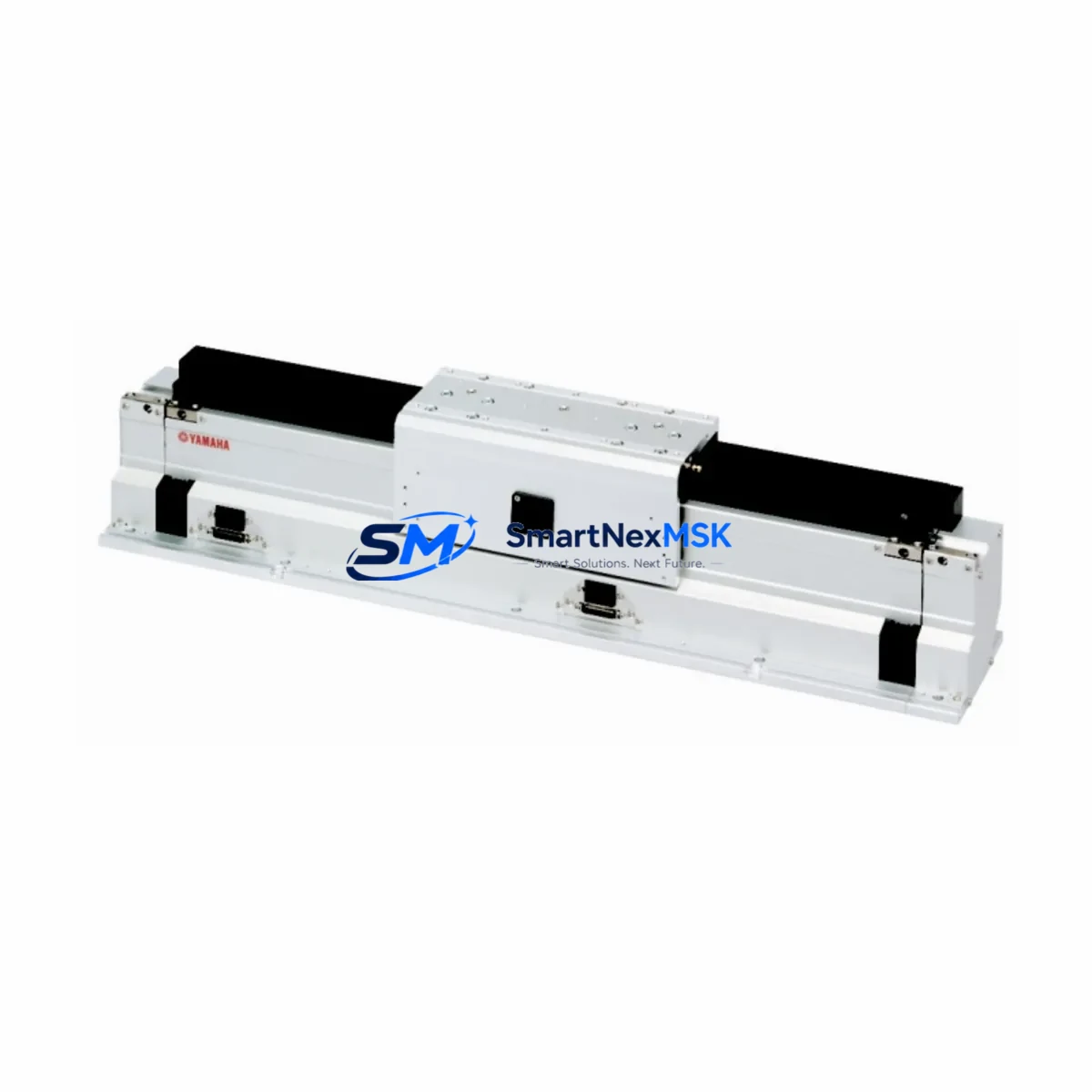
YAMAHA LCC140-10 Retrofit-Ready Linear Conveyor for LCM100 Series Control Systems
The YAMAHA LCC140-10 is a precision linear conveyor module engineered for seamless integration into existing LCM100 Series automation platforms. As production lines age and original components reach end-of-life, the LCC140-10 provides a verified retrofit path that preserves your existing wiring topology, mechanical mounting footprint, and motion control logic — dramatically reducing the engineering effort and downtime associated with legacy system upgrades.
Whether you are replacing a failed unit on a live production line, upgrading a multi-axis conveyor cell, or migrating from an older YAMAHA LCM100 platform to a more capable configuration, the LCC140-10 is designed to slot into your existing infrastructure with minimal rework. Its compatibility with YAMAHA’s established motion controller ecosystem means that program logic developed for earlier LCM100-series deployments can typically be retained with only minor parameter adjustments, protecting your software investment and reducing re-commissioning time on the shop floor.
Upgrade Compatibility Table
| Parameter | LCC140-10 (Current) | LCM100 Series (Legacy) | Retrofit Notes |
|---|---|---|---|
| Mounting Interface | Standard LCM-series rail mount | Standard LCM-series rail mount | Direct mechanical drop-in; no bracket modification required |
| Connector Type | Multi-pin servo/encoder connector | Multi-pin servo/encoder connector | Verify pin-out against original wiring diagram before connection |
| Communication Protocol | YAMAHA proprietary motion bus | YAMAHA proprietary motion bus | Compatible with existing YAMAHA RCX series and YHX controllers |
| Power Supply Requirement | DC 24V control / AC servo drive | DC 24V control / AC servo drive | Confirm existing power supply capacity before installation |
| Stroke / Travel | 140mm nominal stroke | Varies by LCM100 variant | Confirm stroke compatibility with your specific LCM100 sub-model |
| Installation Orientation | Horizontal / vertical configurable | Horizontal / vertical configurable | No change to mounting orientation required |
| Debugging Requirement | Parameter re-entry via YAMAHA programming software | Original parameter file | Retain original parameter backup; re-upload after installation |
| Warranty | 12-Month Warranty from date of shipment | Covers manufacturing defects and functional failure under normal use | |
Retrofit Planning for Existing Automation Systems
A successful LCC140-10 retrofit begins well before the module arrives on site. Engineers should start by pulling the original wiring schematics for the LCM100 installation and cross-referencing terminal assignments against the LCC140-10 connector layout. In most configurations, the servo motor cable, encoder feedback cable, and 24V I/O wiring can be reconnected without modification, but it is essential to verify each terminal individually rather than assuming a one-to-one match.
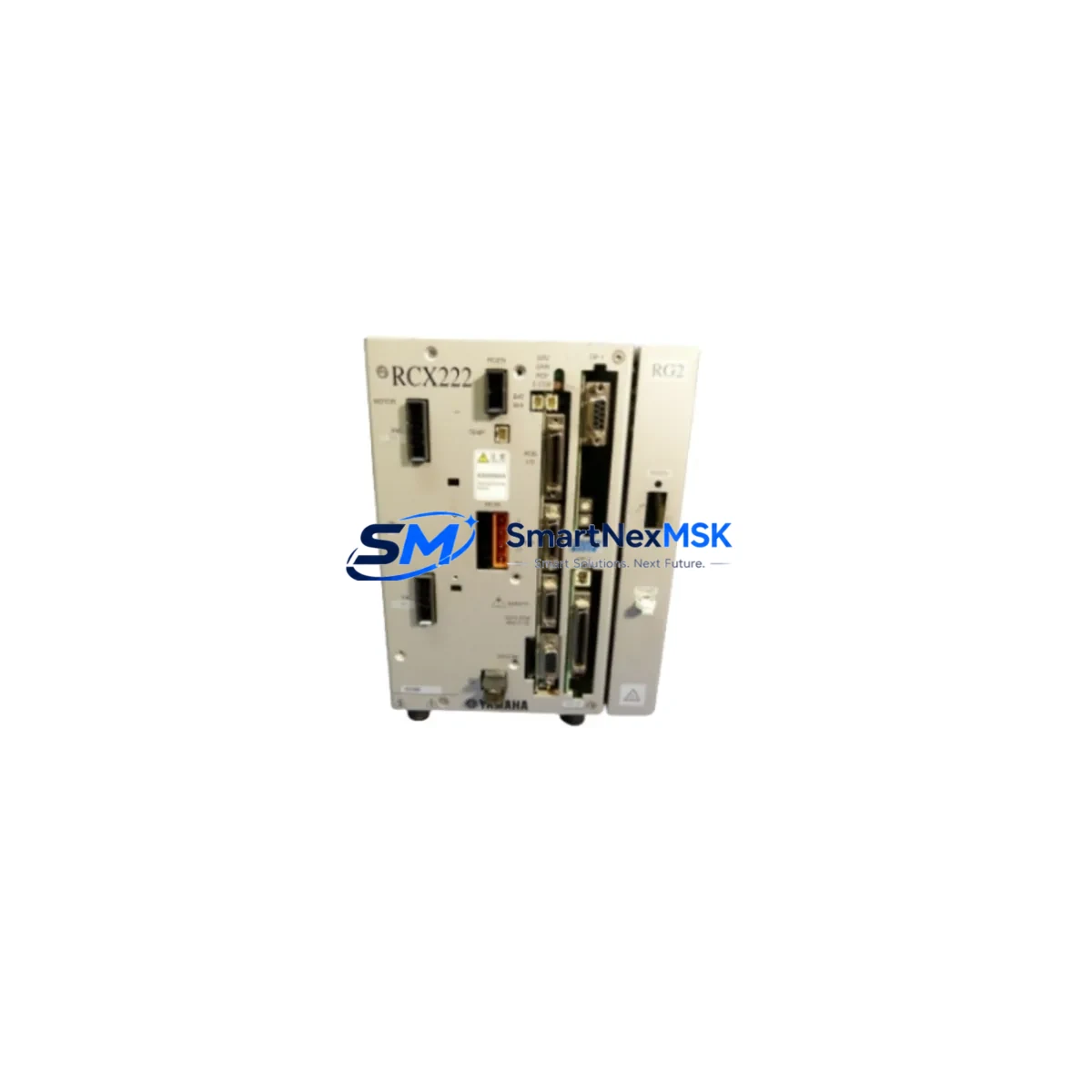
The control cabinet housing the LCM100 typically includes a YAMAHA RCX series motion controller or a compatible YHX-series controller, along with a dedicated servo amplifier or driver module. Before removing the legacy conveyor module, confirm that the servo driver’s axis parameters — including acceleration/deceleration profiles, in-position window, and torque limits — are saved to a backup file. These parameters will need to be re-entered or uploaded to the controller after the LCC140-10 is installed and powered on.
For systems that include a YAMAHA TS series SCARA robot or a multi-axis gantry coordinated with the conveyor, pay particular attention to the synchronization timing between the conveyor’s home position signal and the robot’s pick-and-place cycle. Any change in the conveyor’s homing behavior or position feedback offset can disrupt upstream and downstream handshaking. Review the PLC ladder logic or motion program — often running on a YAMAHA MPX or compatible Mitsubishi MELSEC Q-series PLC — to identify any hard-coded position references that may need updating.
I/O wiring between the LCC140-10 and the host PLC typically involves digital inputs for home sensor, limit switches, and workpiece detection, as well as digital outputs for conveyor enable and fault reset. If the existing system uses a remote I/O terminal block or a distributed I/O module mounted on a DIN rail inside the control cabinet, verify that the I/O address mapping in the PLC program matches the physical wiring of the new module. In installations where a YAMAHA NETC01-CC or similar CC-Link communication module is used for remote I/O, confirm that the station address and baud rate settings are preserved during the swap.
HMI screens — whether running on a Proface GP series, Keyence VT series, or a YAMAHA-integrated touch panel — may display conveyor status, position feedback, and alarm codes that are mapped to specific PLC data registers. After the LCC140-10 is commissioned, verify that all HMI displays are reading correctly and that alarm messages correspond to the new module’s fault codes. Update any HMI project files if the fault code mapping has changed between the LCM100 and LCC140-10 generations.
For facilities running a 24/7 production schedule, pre-staging the LCC140-10 on a test bench before the scheduled maintenance window is strongly recommended. Bench-test the module with a compatible servo driver and controller, confirm homing and positioning accuracy, and validate the I/O signal behavior before bringing the unit to the production floor. This approach allows the actual on-site swap to be completed within a single planned downtime window, typically two to four hours for an experienced technician.
Downtime Control During System Migration
Minimizing production interruption during a conveyor module replacement requires a structured approach to pre-work, execution, and post-installation verification. The most effective strategy is to treat the LCC140-10 installation as a planned maintenance event rather than an emergency repair, even when the replacement is triggered by an unexpected failure of the original LCM100 unit.
Begin by creating a pre-installation checklist that covers: backup of all controller parameters and PLC programs, photographic documentation of existing wiring, confirmation of spare parts availability (including any terminal ferrules, cable ties, and mounting hardware), and notification to downstream production cells that a brief stoppage is planned. Having a YAMAHA programming cable and a laptop loaded with the appropriate YAMAHA RCX or YHX programming software on hand before the maintenance window opens will eliminate delays caused by last-minute equipment searches.
During the swap, work systematically from the control cabinet outward. Disconnect and label each cable before removal, install the LCC140-10 in the vacated mounting position, reconnect cables in reverse order, and perform a visual inspection of all terminal connections before applying power. Power up the servo driver first with the motion controller in a safe, inhibited state, then enable the axis and execute a slow-speed homing cycle to confirm that the home sensor and limit switches are functioning correctly. Only after a successful homing cycle should the full motion program be re-enabled and production speed restored.
Post-installation, run the conveyor through at least ten complete positioning cycles at reduced speed before returning to full production rate. Log the actual position feedback values and compare them against the original baseline data to confirm that the LCC140-10 is performing within specification. Document the installation date, module serial number, and any parameter changes made during commissioning — this record will be essential for future maintenance planning and for validating the 12-month warranty coverage.
Retrofit Support FAQ
Q1: Is the LCC140-10 a direct drop-in replacement for all LCM100 Series variants?
The LCC140-10 is mechanically and electrically compatible with the majority of LCM100 Series installations, but compatibility should be verified against your specific LCM100 sub-model and stroke configuration. We recommend sharing your original model number and wiring diagram with our technical team before ordering to confirm suitability. All units are function-tested prior to shipment.
Q2: What debugging steps are required after installation?
After mechanical installation and wiring reconnection, you will need to re-enter or upload the servo axis parameters (acceleration, deceleration, in-position window, torque limit) via the YAMAHA programming software. Execute a homing cycle at reduced speed, verify position feedback accuracy, and confirm I/O signal behavior before resuming production. Our technical support team can provide guidance on parameter settings specific to your application.
Q3: Can the existing PLC program and HMI project be used without modification?
In most cases, the existing PLC ladder logic and HMI project files can be retained without modification, provided that the I/O address mapping and data register assignments are consistent between the LCM100 and LCC140-10 configurations. If your system uses CC-Link or other fieldbus communication, verify that the station address and baud rate settings are unchanged. Minor updates to fault code mappings in the HMI may be required depending on your specific installation.
Q4: What does the 12-month warranty cover, and what is the shipping timeline?
All LCC140-10 units supplied by SMARTNEXMSK carry a 12-month warranty from the date of shipment, covering manufacturing defects and functional failure under normal operating conditions. Units are inspected and function-tested before dispatch. We maintain ready stock in Xiamen and can typically ship within 1–3 business days of order confirmation. Express international shipping options are available to minimize lead time for urgent retrofit projects.
© 2026 SMARTNEXMSK. All rights reserved.
Original Source: https://smartnexmsk.com
Contact: sales@smartnexmsk.com | +86 18259474341