Zeiss 348224-9113-1302 Maintenance-Ready Spare for VAC Automation
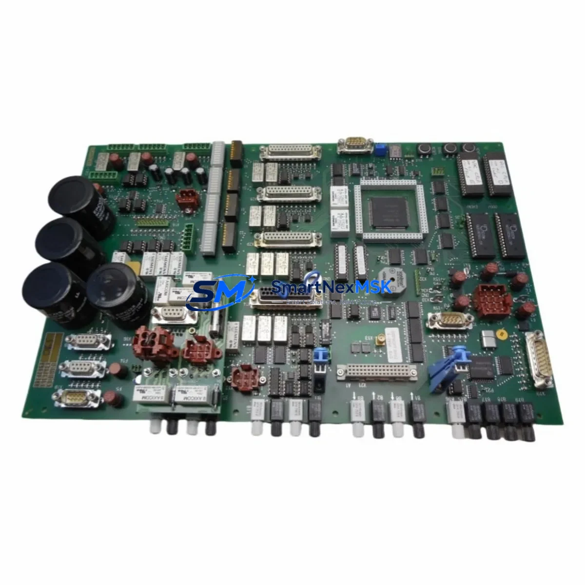
The Zeiss 348224-9113-1302 is an original VAC Control Board PCB designed for precision optical and semiconductor automation systems. For maintenance engineers managing aging Zeiss platforms, unplanned downtime caused by a failed control board can halt production lines for days. Stocking a verified replacement of the 348224-9113-1302 is a proven strategy to compress mean time to repair (MTTR) and restore system availability without waiting on extended lead times from OEM channels.
This board governs vacuum regulation logic within the Zeiss VAC subsystem, interfacing directly with pressure sensors, solenoid valve drivers, and interlock circuits. When the board fails, symptoms typically include vacuum fault alarms, erratic pressure readings, loss of chuck or stage hold, and system-level E-stop conditions. Identifying the 348224-9113-1302 as the root cause requires systematic fault isolation — ruling out upstream power supply anomalies, downstream sensor wiring faults, and communication errors before condemning the board itself.
Each unit supplied by SMARTNEXMSK undergoes functional verification prior to dispatch. The board is shipped with ESD-safe packaging, inspection documentation, and is covered by a 12-month warranty against manufacturing defects and functional failure. Long-term supply continuity is maintained through established sourcing channels, making this a reliable option for both emergency replacement and planned spare parts inventory programs.
Spare Maintenance Table
| Parameter | Specification / Notes |
|---|---|
| Part Number | 348224-9113-1302 |
| Manufacturer | Zeiss (Carl Zeiss AG) |
| Function | VAC (Vacuum) Control Board / PCB |
| Product Type | Industrial Control PCB — Spare Part |
| Compatible Systems | Zeiss VAC-series precision optical & semiconductor automation platforms |
| Origin | Germany (DE) |
| Board Weight | Approx. 1,850 g (packaged) |
| Installation Environment | Controlled cleanroom or industrial cabinet; ESD-sensitive |
| Interface | Pressure sensor inputs, solenoid valve outputs, interlock I/O, internal bus |
| Replacement Scope | Direct drop-in for failed or degraded 348224-9113-1302 boards |
| Pre-shipment Testing | Functional verification performed on every unit |
| Warranty | 12 Months — covers functional failure and manufacturing defects |
| Packaging | ESD-safe anti-static bag, foam-lined carton |
| Lead Time | In-stock units ship within 2–5 business days |
| Supply Continuity | Long-term sourcing maintained for legacy system support |
Maintenance Planning for Continuous Operation
Replacing the 348224-9113-1302 VAC Control Board is rarely an isolated task. A disciplined maintenance engineer will use the board replacement event as an opportunity to inspect the entire vacuum control circuit and adjacent subsystems. Before reinstalling a new board, verify the integrity of the 24 VDC power supply rail feeding the VAC subsystem — a marginal power supply is a common root cause of repeated board failures. Check the fuse block and circuit breakers protecting the VAC control circuit, as overcurrent events can damage the replacement board if the upstream fault is not cleared.
Inspect all wiring harnesses and connector pins at the board interface. Corroded or loose connectors on pressure transducer signal lines can introduce noise that mimics board faults. If the system uses a Zeiss-compatible signal isolator or analog input conditioner between the sensor and the board, verify its output range and calibration. I/O terminal blocks on the interlock circuit should be checked for tightness and signs of thermal stress.
For systems where the VAC board communicates with a higher-level PLC or motion controller via a fieldbus or discrete I/O, confirm that the communication module — whether a PROFIBUS DP adapter, DeviceNet node, or EtherCAT slave — is functioning correctly and that no address conflicts exist after the board swap. If the system includes a Zeiss HMI or operator panel, verify that vacuum status displays and alarm acknowledgment functions respond correctly after the replacement.
Solenoid valve coils in the vacuum circuit should be resistance-tested during the maintenance window. A shorted coil can load the board’s output driver and cause premature failure. Similarly, inspect the vacuum pump motor starter or VFD for fault history that may indicate mechanical stress on the vacuum system. Relay modules in the interlock chain — particularly those handling E-stop and door interlock signals — should be exercised and checked for contact wear. Terminal strips and DIN rail-mounted components in the same control cabinet should be visually inspected for signs of overheating, condensation, or insulation degradation.
Maintaining a minimum spare parts inventory that includes the 348224-9113-1302 board alongside a compatible power supply module, a set of solenoid valve coils, and a spare pressure transducer provides a comprehensive first-response kit for vacuum system failures — reducing unplanned downtime from days to hours.
Site Replacement Workflow
Step 1 — Fault Confirmation: Retrieve active alarms from the system HMI or PLC diagnostic screen. Confirm that the vacuum fault is board-related and not caused by a sensor, valve, or mechanical pump fault. Document the fault codes before powering down.
Step 2 — Safe Isolation: Follow the system’s lockout/tagout (LOTO) procedure. Isolate the VAC control cabinet from mains power. Discharge any residual capacitance on the power supply bus before handling the PCB.
Step 3 — Board Removal: Photograph connector positions and cable routing before disconnection. Label all connectors if not already marked. Remove the 348224-9113-1302 board using ESD-safe tools and place it in an anti-static bag for return or failure analysis.
Step 4 — Inspection & Pre-installation Check: Inspect the board slot, backplane connectors, and mounting hardware for damage. Verify the replacement board’s part number matches 348224-9113-1302 exactly. Check for any DIP switch or jumper settings that must be replicated from the removed board.
Step 5 — Installation & Power-up: Seat the replacement board firmly. Reconnect all harnesses in the documented order. Restore power and observe the system startup sequence. Confirm that vacuum fault alarms clear and that the VAC subsystem reaches normal operating pressure within the expected time window.
Step 6 — Functional Verification: Run the system through a full vacuum cycle. Verify pressure readings on the HMI match expected values. Confirm interlock signals are active and that the system passes its self-test or qualification routine before returning to production.
Step 7 — Documentation: Record the replacement in the equipment maintenance log. Note the serial number of the removed board, the date of replacement, and the fault symptoms observed. Update the spare parts inventory to trigger reorder of a replacement stock unit.
Spare Parts Support FAQ
Q1: What is the expected service life of the 348224-9113-1302 board, and when should I plan a proactive replacement?
The board does not have a fixed OEM-published MTBF for field replacement, but in high-cycle vacuum automation environments, control boards in this class typically see degradation after 8–12 years of continuous operation. Proactive replacement is recommended when the system shows intermittent vacuum faults that clear on reset, or when the board is identified as a single point of failure in a critical production line with no hot spare available.
Q2: How do I confirm compatibility before ordering a replacement?
Match the full part number — 348224-9113-1302 — against the label on the installed board and the system’s spare parts list or BOM. If the system has undergone a revision, check whether the board revision suffix has changed. Contact SMARTNEXMSK at sales@smartnexmsk.com with your system model and board label photograph for compatibility confirmation before ordering.
Q3: What pre-shipment testing is performed, and what documentation is included?
Every 348224-9113-1302 unit is functionally tested prior to dispatch. Shipments include an inspection record confirming the test result. Units are packaged in ESD-safe materials and shipped with a 12-month warranty certificate. Expedited shipping options are available for emergency downtime situations.
Q4: Can SMARTNEXMSK support long-term supply for legacy Zeiss systems?
Yes. SMARTNEXMSK maintains sourcing relationships that support legacy and discontinued Zeiss spare parts. For facilities managing multiple Zeiss platforms or planning a multi-year maintenance contract, we can discuss blanket order arrangements and reserved inventory programs to ensure supply continuity without repeated spot-market procurement.
© 2026 SMARTNEXMSK. All rights reserved.
Original Source: https://smartnexmsk.com
Contact: sales@smartnexmsk.com | +86 18259474341