ZENTRO ELEKTRIK MOD.8899-2/A.NO.98128899100 Maintenance-Ready Spare for MOD.8899 Automation
The ZENTRO ELEKTRIK MOD.8899-2/A.NO.98128899100 is an original signal converter module designed for continuous-duty industrial automation environments. As a maintenance-ready spare, it is sourced, inspected, and dispatched to support rapid field replacement in PLC-based and DCS-integrated control systems where signal integrity and uptime are non-negotiable. Whether you are managing a scheduled overhaul, responding to an unplanned fault, or building a strategic spare parts buffer, this module delivers the compatibility and reliability that maintenance and procurement engineers depend on.
Signal converter modules in the MOD.8899 series serve as the interface layer between field instrumentation and the control system’s I/O infrastructure. A failure in this component can disrupt analog signal chains, trigger false alarms, or cause complete loss of process visibility — all of which translate directly into unplanned downtime and production loss. Stocking a verified replacement unit of the MOD.8899-2/A.NO.98128899100 is a proven strategy for reducing mean time to repair (MTTR) and maintaining system availability across aging and active installations alike.
Each unit is dispatched after functional verification and packed for safe transit. A 12-month warranty is included as standard, covering manufacturing defects and operational failures under normal industrial use conditions.
Spare Maintenance Table
| Part Number | MOD.8899-2/A.NO.98128899100 |
| Brand | ZENTRO ELEKTRIK |
| Series | MOD.8899 |
| Product Type | Signal Converter Module |
| Country of Origin | Germany (DE) |
| Weight | 2,900 g |
| Application | Industrial signal conversion, PLC/DCS I/O interface, analog signal conditioning |
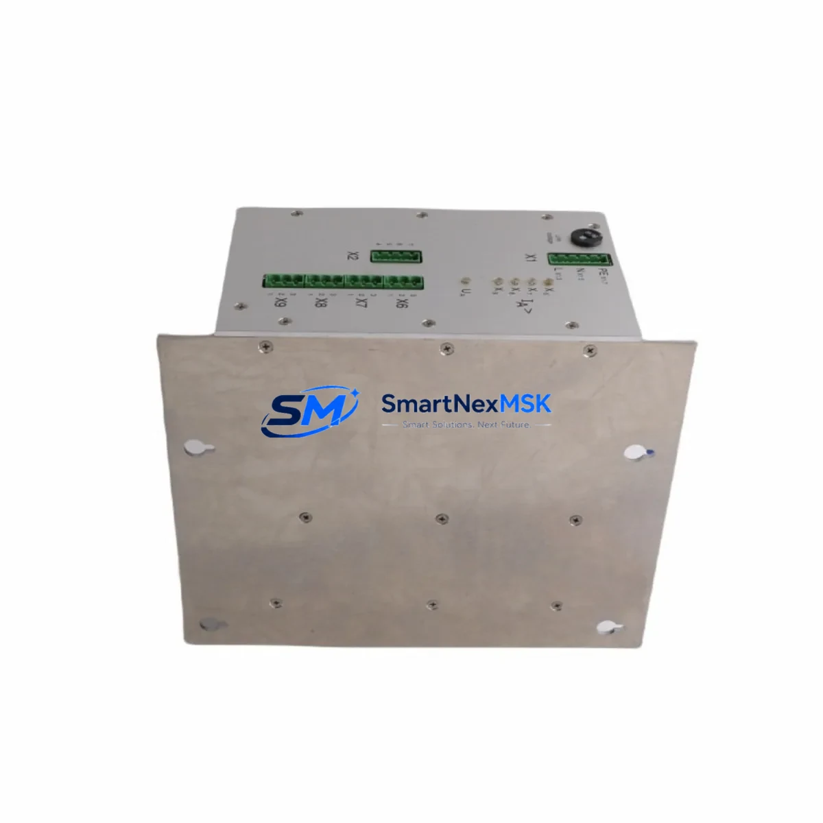
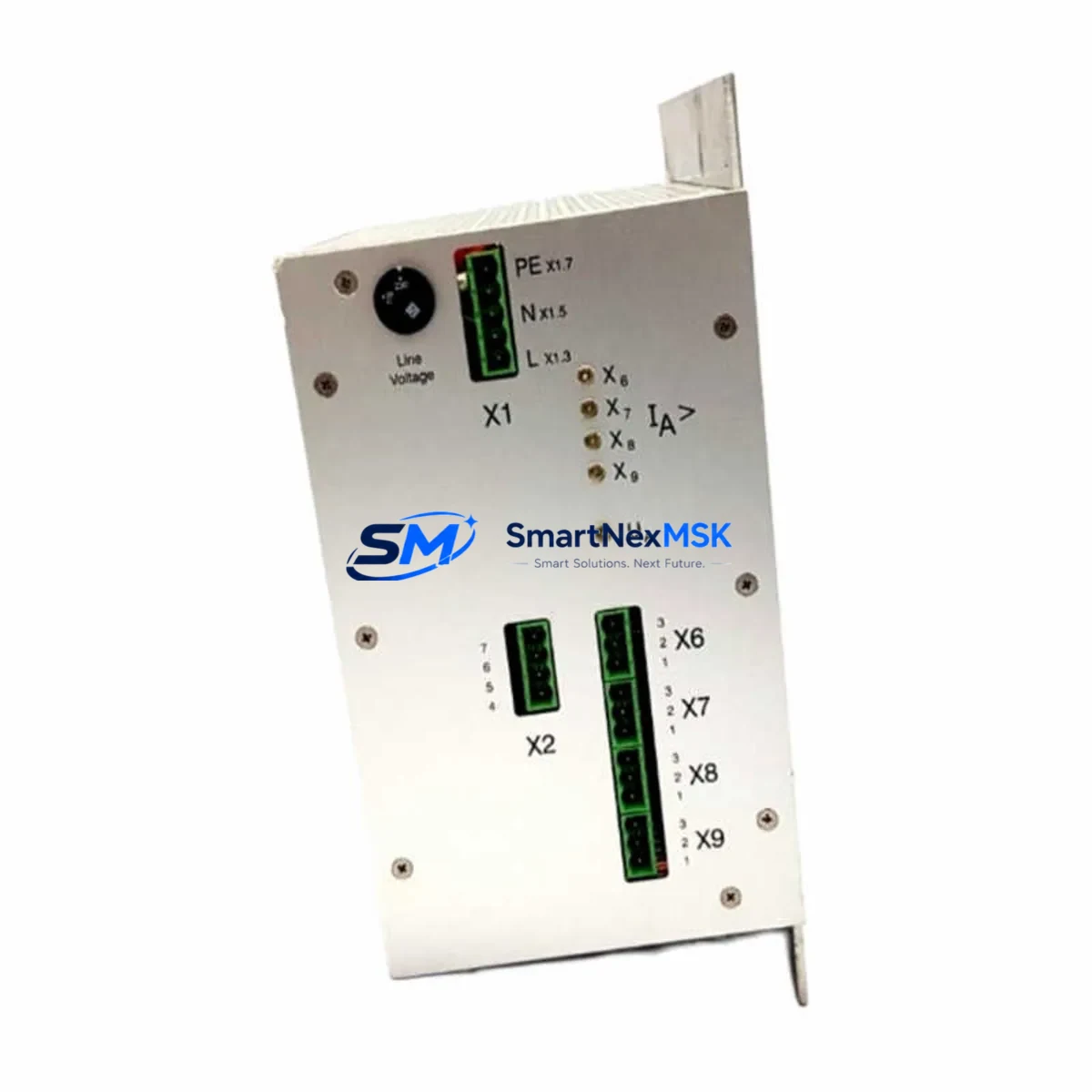
| Compatibility | MOD.8899 series control systems; suitable for retrofit and direct replacement in existing panel layouts |
| Installation | DIN rail or panel mount; refer to OEM wiring diagram for terminal assignments |
| Operating Environment | Industrial control cabinet; standard IEC operating temperature and humidity ranges |
| Maintenance Recommendation | Inspect signal output accuracy during scheduled PM; replace if drift exceeds tolerance or module fails self-test |
| Condition | Original, new or equivalent-grade tested spare |
| Warranty | 12 Months — covers manufacturing defects and operational failure under normal use |
| Dispatch | Tested before shipment; secure industrial packaging |
Maintenance Planning for Continuous Operation
When replacing the MOD.8899-2/A.NO.98128899100 in the field, a thorough inspection of the surrounding electrical circuit is essential to prevent repeat failures and confirm system integrity. Maintenance engineers should treat this replacement as an opportunity to audit the full signal chain and associated power infrastructure within the control cabinet.
Begin by verifying the 24 VDC power supply module feeding the signal converter rail — voltage sag or ripple is a common root cause of converter instability. Check the terminal blocks and wiring ferrules on the input and output sides of the module for corrosion, loose crimps, or thermal discoloration. If the installation uses signal isolators upstream of the MOD.8899-2, confirm their output range and loop resistance are within specification, as mismatched isolators can cause calibration drift after module swap.
Inspect the analog I/O module on the PLC or DCS side that receives the converted signal. A degraded I/O channel can mask a successful module replacement and lead to misdiagnosis. Similarly, review the communication module or fieldbus gateway if the signal chain feeds a PROFIBUS, PROFINET, or Modbus network node — firmware version mismatches can cause intermittent data loss after hardware changes.
For cabinets with relay output modules or solid-state relay (SSR) banks in the same enclosure, verify that switching transients are adequately suppressed with RC snubbers or varistors, as these transients can accelerate converter module aging. Check the fuse holders and miniature circuit breakers (MCBs) protecting the signal converter circuit — a marginally rated or aging fuse may not have tripped but could be contributing to intermittent supply interruptions.
If the system includes an HMI panel displaying process values derived from this signal chain, recalibrate the display scaling after module replacement to confirm end-to-end signal accuracy. For older installations where the MOD.8899 series has been in service for more than five years, consider scheduling a full cabinet thermal scan and reviewing the spare parts list for companion modules such as analog output modules, signal conditioners, and backplane connectors that share the same service life profile.
Site Replacement Workflow
Step 1 — Isolation: De-energize the relevant circuit following your site LOTO (Lockout/Tagout) procedure. Confirm zero voltage at the module terminals before proceeding.
Step 2 — Documentation: Photograph or record all wiring connections, terminal labels, and DIP switch or jumper settings on the existing module before removal. This is critical for restoring the exact configuration on the replacement unit.
Step 3 — Removal: Disconnect field wiring in sequence, label each conductor, and remove the module from its mounting position. Retain the old unit for failure analysis if root cause investigation is required.
Step 4 — Configuration: Set the replacement MOD.8899-2/A.NO.98128899100 to match the documented switch and jumper positions. Verify input/output range selection matches the field instrument and PLC I/O channel specifications.
Step 5 — Installation and Wiring: Mount the new module, reconnect field wiring in reverse removal order, and torque terminals to specification. Confirm cable routing avoids high-voltage conductors and EMI sources.
Step 6 — Energization and Verification: Re-energize the circuit and confirm the module powers up without fault indication. Apply a known reference signal and verify the output at the PLC/DCS I/O channel matches the expected engineering unit value.
Step 7 — System Handover: Update the maintenance log, record the replacement date and new module serial number, and return the system to normal operation. Replenish the spare parts stock to maintain buffer inventory.
This workflow minimizes downtime exposure and ensures the replacement is traceable and auditable — a requirement in ISO 9001 and IEC 62443 compliant maintenance programs.
Spare Parts Support FAQ
Q1: Is the MOD.8899-2/A.NO.98128899100 a direct drop-in replacement for the original installed unit?
Yes. This spare is sourced to match the original OEM specification for the MOD.8899 series. Verify DIP switch and jumper settings against your site documentation before installation to ensure the signal range and output type are correctly configured for your application.
Q2: What does the 12-month warranty cover, and how is a warranty claim handled?
The 12-month warranty covers manufacturing defects and operational failures arising under normal industrial operating conditions. If a unit fails within the warranty period, contact our sales team with the order reference and a description of the fault. We will arrange a replacement dispatch or technical review as appropriate.
Q3: How do you verify the module is functional before shipment?
Each unit undergoes a pre-dispatch functional check to confirm power-up behavior and signal conversion performance. Units that do not pass inspection are not dispatched. Test records are available on request for quality-critical procurement processes.
Q4: Can you support long-term or blanket orders for this spare part?
Yes. We support scheduled delivery agreements and buffer stock arrangements for maintenance teams managing aging MOD.8899 series installations. Contact our team to discuss volume pricing, lead time commitments, and consignment stock options suited to your planned maintenance cycle.
© 2026 SMARTNEXMSK. All rights reserved.
Original Source: https://smartnexmsk.com
Contact: sales@smartnexmsk.com | +86 18259474341