ABB 1KHL015502R0004 Retrofit-Ready I/O Coupler for AC500 Control Systems
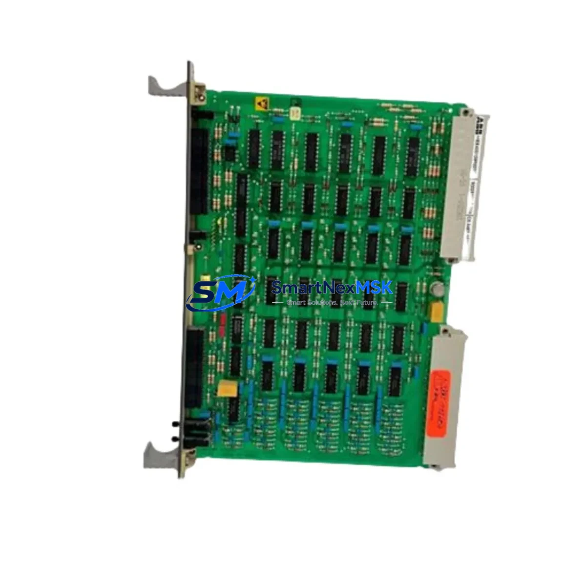
The ABB 1KHL015502R0004 (also identified as N4BDTEBIT) is a high-performance I/O coupler module designed for the ABB AC500 PLC platform. As legacy automation systems reach end-of-life and original spare parts become increasingly difficult to source, this module serves as a verified retrofit-ready replacement for facilities managing aging control infrastructure. Whether you are upgrading a discontinued control cabinet, migrating from an older AC500 generation, or restoring a production line after an unplanned failure, the 1KHL015502R0004 provides a reliable, specification-matched solution with minimal engineering rework.
This module functions as the communication bridge between the AC500 CPU — such as the PM573, PM583, or PM591 — and distributed I/O terminal bases. It supports the internal I/O bus architecture of the AC500 system, enabling seamless integration with TB711 and TB721 terminal bases already installed in the field. For sites running mixed generations of AC500 hardware, the 1KHL015502R0004 maintains backward compatibility with existing rack configurations, reducing the need for full panel redesigns.
Before installation, engineers should verify the following during retrofit planning: power supply capacity on the existing 24 VDC rail (typically supplied by a CP-E 24/5.0 or equivalent ABB power supply module), terminal wiring assignments on the existing I/O terminal base, backplane slot addressing to ensure the module address matches the original configuration in the PLC program, and communication link integrity between the coupler and the CPU module. If the site uses a CS31 bus coupler or PROFIBUS DP adapter for remote I/O, the coupler address must be re-confirmed after module swap to avoid address conflicts.
Program compatibility is a critical checkpoint. The original Automation Builder project file should be reviewed to confirm that the I/O mapping for the replaced coupler slot remains intact. In most AC500 retrofit scenarios, no program modification is required if the physical slot position and module type are preserved. However, if the original module was configured with a non-default I/O bus cycle time, this parameter should be re-entered in the hardware configuration editor before downloading to the CPU.
HMI screen updates are generally not required for a like-for-like coupler replacement, but if the retrofit involves expanding I/O capacity — for example, adding additional DI524 digital input modules or AO523 analog output modules to the same rack — the HMI tag database and screen bindings should be reviewed and updated accordingly. Communication links to upstream SCADA systems via Modbus TCP or OPC UA should be tested after power-up to confirm that data exchange resumes without manual intervention.
On-site commissioning typically follows a structured sequence: visual inspection of the module seating on the terminal base, power-on self-test confirmation via LED status indicators, CPU recognition of the new module in the hardware scan, I/O force test for each channel, and final sign-off with a live production run under supervision. Our team provides pre-shipment functional testing on all units, and each module ships with a 12-month warranty covering manufacturing defects and operational failures under normal industrial conditions.
Upgrade Compatibility Table
| Parameter | Details |
|---|---|
| Module Part Number | 1KHL015502R0004 (N4BDTEBIT) |
| Compatible PLC Platform | ABB AC500 Series (PM573, PM583, PM591, PM595) |
| Compatible Terminal Bases | TB711, TB721 |
| Backplane Interface | AC500 Internal I/O Bus |
| Communication Compatibility | CS31, PROFIBUS DP, Modbus TCP, OPC UA (via CPU) |
| Power Supply Requirement | 24 VDC (verify rail capacity before installation) |
| Installation Type | DIN Rail / Rack-mounted on AC500 terminal base |
| Replacement Recommendation | Direct drop-in for same-slot AC500 I/O coupler positions |
| Commissioning Notes | Verify slot address, re-download hardware config if required |
| Warranty | 12 Months — manufacturing defects & operational failures |
Retrofit Planning for Existing Automation Systems
Successful retrofit of the ABB 1KHL015502R0004 into an existing control system requires a structured assessment of the surrounding hardware ecosystem. In a typical AC500-based control cabinet, the coupler module works in concert with a range of components that must be evaluated before and after the swap.
Start with the power distribution architecture. The CP-E 24/5.0 or CP-E 24/10.0 power supply modules feeding the I/O rack must have sufficient headroom to support the replacement coupler plus any additional I/O modules being added during the same maintenance window. Overloaded power rails are a common cause of intermittent faults after retrofit work.
Next, assess the rack and backplane configuration. The AC500 system uses modular racks that accommodate the CPU, coupler, and I/O modules in a defined slot order. If the original rack — for example a TB724 or TB726 terminal base assembly — has unused slots, this retrofit window is an ideal opportunity to add DI524 digital input modules or DO524 digital output modules to expand I/O capacity without additional wiring infrastructure changes.
For sites with remote I/O nodes connected via PROFIBUS DP, the CI502-PNIO or CI504-PNIO PROFINET adapter modules should be checked for firmware compatibility with the replacement coupler. Similarly, if the plant uses DeviceNet or legacy CS31 bus topology, the coupler address settings must be re-verified against the master station configuration.
Analog signal chains connected through AI523 analog input modules or AO523 analog output modules should be loop-tested after the coupler replacement to confirm signal integrity. Any calibration offsets stored in the original module configuration must be re-entered if the replacement module does not retain non-volatile parameter storage from the previous unit.
Finally, if the control system includes an ABB CP600 or CP620 HMI panel communicating directly with the AC500 CPU, verify that the HMI project’s communication driver settings remain unchanged after the coupler swap. In most cases, the HMI communicates with the CPU — not the coupler — so no HMI project modification is required for a standard coupler replacement.
Downtime Control During System Migration
Minimizing production downtime during a coupler module replacement is achievable with proper pre-staging and a disciplined switchover procedure. The recommended approach is to prepare the replacement 1KHL015502R0004 module off-line before the scheduled maintenance window: confirm the module powers up correctly on a test bench, verify LED status indicators, and if possible, load the existing hardware configuration from the Automation Builder project to pre-validate the module’s response.
During the switchover, follow a controlled power-down sequence: save the current CPU program to a memory card or laptop, power down the I/O rack (not necessarily the entire panel if other control zones are active), remove the faulty coupler, seat the replacement module firmly on the terminal base, and restore power. The AC500 CPU will perform an automatic hardware scan on power-up. If the new module is recognized without errors, the system will resume normal operation within seconds.
To protect original program logic, always maintain a backup of the Automation Builder project file — including hardware configuration, POU code, and variable tables — on a dedicated engineering laptop or network share before beginning any physical work. This ensures that if the CPU requires a full program reload after the swap, the exact pre-retrofit logic can be restored without reconstruction from memory.
For critical production lines where even brief interruptions are costly, consider staging a pre-configured spare rack assembly with the 1KHL015502R0004 already installed and addressed. This allows a complete rack swap rather than a module-level swap, reducing hands-on time at the panel from potentially 30–60 minutes to under 10 minutes. All units supplied by SMARTNEXMSK undergo pre-shipment functional testing to support this hot-swap staging strategy.
Retrofit Support FAQ
Q1: Is the 1KHL015502R0004 a direct replacement for the original ABB AC500 I/O coupler in the same slot position?
Yes. The 1KHL015502R0004 (N4BDTEBIT) is designed as a direct slot-compatible replacement for the corresponding AC500 I/O coupler position. No mechanical modification to the terminal base or rack is required. Verify the slot address in your Automation Builder hardware configuration matches the physical installation position before downloading.
Q2: Do I need to modify my PLC program after replacing the coupler module?
In most cases, no program modification is required for a like-for-like replacement. The I/O mapping, variable assignments, and communication parameters remain valid as long as the module type and slot position are unchanged. If the original module had custom I/O bus cycle time settings, re-enter those parameters in the hardware configuration editor before the next program download.
Q3: What pre-shipment testing is performed on each unit?
Every 1KHL015502R0004 module supplied by SMARTNEXMSK undergoes functional power-on testing, LED status verification, and communication interface checks prior to shipment. Units are packed in anti-static protective packaging with inspection documentation. A 12-month warranty covers manufacturing defects and operational failures under normal industrial operating conditions.
Q4: Can this module be used with both older and newer AC500 CPU generations?
The 1KHL015502R0004 is compatible with the AC500 V2 and V3 CPU families, including PM573, PM583, PM591, and PM595 variants. For AC500-eCo or AC500-S (safety) platforms, compatibility should be confirmed against the specific system configuration before ordering. Contact our technical team at sales@smartnexmsk.com for application-specific compatibility confirmation.
© 2026 SMARTNEXMSK. All rights reserved.
Original Source: https://smartnexmsk.com
Contact: sales@smartnexmsk.com | +86 18259474341


