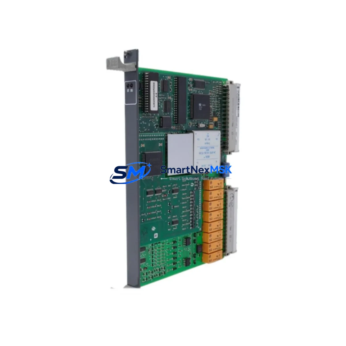
ABB GJR2396200R1210 Retrofit-Ready I/O Module for AC500 Control Systems
The ABB GJR2396200R1210 (83SR51F-E) is a proven I/O module designed for seamless integration into ABB AC500 PLC control systems. Whether you are replacing a failed unit on an aging production line, upgrading a legacy control cabinet, or executing a planned system modernization, this module delivers the compatibility, reliability, and performance that industrial automation engineers demand. With verified compatibility across the AC500 platform and a 12-month warranty, it is a trusted choice for retrofit projects where downtime must be minimized and control continuity is non-negotiable.
Upgrade Compatibility Table
| Parameter | Details |
|---|---|
| SKU / Part Number | GJR2396200R1210 (83SR51F-E) |
| Series Compatibility | ABB AC500 PLC Platform |
| Module Type | Digital / Analog I/O Module |
| Backplane Interface | AC500 S500 I/O Bus |
| Installation Requirement | DIN rail or panel mount; compatible with TB511, TB521, TB541 terminal bases |
| Communication Compatibility | PROFIBUS-DP, Modbus RTU, CANopen (via AC500 CPU) |
| Replacement Recommendation | Direct drop-in for same-series legacy I/O modules; verify terminal base revision |
| Commissioning Notes | Re-address module slot in PS501 Control Builder; verify I/O mapping in existing program |
| Warranty | 12 Months from date of shipment |
Retrofit Planning for Existing Automation Systems
Successful retrofit of the GJR2396200R1210 into an existing AC500 installation requires careful pre-migration planning. Before removing the legacy module, engineers should document the current terminal wiring layout and photograph all field connections. The AC500 platform uses a modular architecture where I/O modules mount onto terminal bases such as the TB511-ETH or TB521 — confirm that the existing terminal base revision is compatible with the replacement unit to avoid mechanical or electrical mismatch.
Power budget verification is a critical first step. The AC500 backplane distributes 24 VDC across all mounted modules; adding or replacing an I/O module may shift the total current draw. Review the power module — typically a PM571, PM581, or PM591 CPU unit — to confirm available headroom. If the control cabinet includes a DC power supply module such as the CP604 or an external 24 VDC rail, verify that the supply rating accommodates the new module’s consumption.
For systems using PROFIBUS-DP or Modbus RTU communication, the module address must be re-confirmed in the network configuration. The AC500 CPU manages I/O addressing through the PS501 Control Builder software; after physical installation, open the hardware configuration, locate the replaced slot, and verify that the GSD file or module descriptor matches the GJR2396200R1210. Any mismatch will prevent the CPU from recognizing the module at startup.
If the existing system includes an HMI panel — such as an ABB CP600 or a third-party SCADA terminal — review all I/O variable bindings that reference the replaced module’s channel addresses. Changes to slot position or module type may require HMI screen updates to maintain accurate process visualization. Similarly, if the control program uses structured data types or function blocks that reference specific I/O addresses, a program review in Control Builder is recommended before going live.
For systems with expanded I/O racks using the S500 bus coupler or a CI590-CS31 communication interface module, confirm that the bus coupler firmware supports the replacement module. Older firmware revisions may not enumerate newer module variants correctly. A firmware update on the bus coupler — performed offline during the maintenance window — eliminates this risk before the new module is powered up.
Finally, prepare a commissioning checklist that covers: terminal torque verification, module LED status confirmation (RUN/ERR indicators), forced I/O test in Control Builder, and a full I/O scan cycle before releasing the line to production. Having a programming cable such as the TK501 or a USB-to-serial adapter on hand ensures that last-minute program adjustments can be made at the panel without returning to the engineering workstation.
Downtime Control During System Migration
Minimizing production downtime during an AC500 I/O module replacement requires a structured hot-swap or cold-swap strategy depending on the system’s safety classification. For non-safety-rated lines, the AC500 CPU can often be placed in STOP mode while the module is swapped, preserving the program in RAM and allowing a rapid restart once the replacement is confirmed operational. For safety-rated or process-critical applications, a parallel wiring approach — where the new module is pre-wired on a temporary terminal strip and validated offline — allows the physical cutover to be completed in minutes rather than hours.
Retain a backup of the current Control Builder project file before any hardware change. The PS501 software supports project export to a local archive; this backup ensures that if the replacement module triggers an unexpected configuration error, the original program can be restored without re-engineering. Where possible, schedule the swap during a planned maintenance window and notify downstream systems — including SCADA, MES, or historian platforms — to suppress false alarms during the transition period.
Retrofit Support FAQ
Q: Is the GJR2396200R1210 a direct replacement for my existing AC500 I/O module?
A: In most AC500 installations, yes. The module is designed for the S500 I/O bus and mounts on standard terminal bases. Confirm the terminal base part number and slot position in your hardware configuration before ordering.
Q: Do I need to modify my existing Control Builder program after installation?
A: If the replacement module occupies the same slot and matches the original module type in the hardware configuration, no program changes are required. If the slot address or module descriptor differs, update the hardware configuration and perform a full download to the CPU.
Q: What wiring checks should I perform before powering up the replacement module?
A: Verify terminal torque to specification, confirm field wiring polarity on all I/O channels, check that the 24 VDC supply to the terminal base is within tolerance (typically 20.4–28.8 VDC), and inspect the backplane connector for bent pins or contamination before seating the module.
Q: What does the 12-month warranty cover?
A: The 12-month warranty covers manufacturing defects and functional failures under normal operating conditions. Each unit undergoes pre-shipment functional testing. Warranty claims are supported by SMARTNEXMSK with replacement or repair at no additional cost within the warranty period.
© 2026 SMARTNEXMSK. All rights reserved.
Original Source: https://smartnexmsk.com
Contact: sales@smartnexmsk.com | +86 18259474341