ABB 1SAY130130R0100-07SS91 Spare for AC500 Automation: Spare Replacement & Industrial Downtime Risk Control
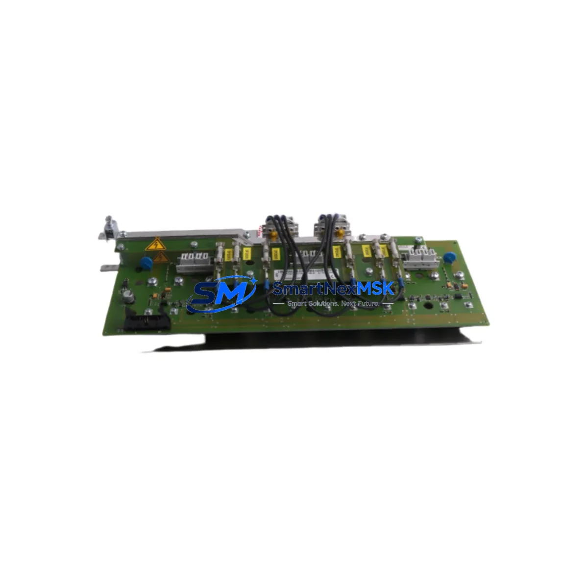
The ABB 1SAY130130R0100-07SS91 is a digital output module designed for the ABB AC500 programmable logic controller series — one of the most widely deployed PLC platforms in process automation, machine control, and critical infrastructure applications. When this module fails or degrades, the downstream impact on production continuity can be immediate and severe. Sourcing a verified, original-spec replacement quickly is the single most effective action a maintenance team can take to restore normal operation.
This listing provides a maintenance-ready, original-specification spare of the 1SAY130130R0100-07SS91, pre-tested before dispatch, backed by a 12-month warranty, and available for fast international shipping. Whether you are executing a planned replacement during a scheduled shutdown or responding to an unplanned fault, this spare is stocked to support your recovery timeline.
Spare Maintenance Table
| Parameter | Specification / Detail |
|---|---|
| Part Number / SKU | 1SAY130130R0100-07SS91 |
| Brand | ABB |
| Series | AC500 |
| Module Type | Digital Output Module |
| Output Channels | Digital DO (transistor or relay, per AC500 DO module standard) |
| Supply Voltage | 24 V DC (nominal, per AC500 platform standard) |
| Compatibility | ABB AC500 PLC CPU modules (PM5xx series); AC500-eCo variants where applicable |
| Mounting | DIN rail, AC500 backplane slot installation |
| Operating Temperature | -25 °C to +60 °C (standard AC500 environmental rating) |
| Protection Class | IP20 (panel-mounted, control cabinet installation) |
| Origin | Germany (ABB manufacturing standard) |
| Condition | Original, new or tested-serviceable spare |
| Pre-Shipment Test | Functional output channel verification performed before dispatch |
| Warranty | 12 months from date of delivery |
| Lead Time | In-stock: same-day or next-business-day dispatch |
| Maintenance Recommendation | Replace at first sign of output channel fault; inspect wiring harness and terminal block on installation |
Maintenance Planning for Continuous Operation
Replacing the 1SAY130130R0100-07SS91 in an AC500 control system is rarely an isolated task. Experienced maintenance engineers treat a DO module fault as a trigger for a broader cabinet inspection. The following components share the same electrical environment and should be evaluated during the same maintenance window:
The AC500 CPU module (PM5xx series) — such as the PM554 or PM564 — should be checked for firmware version compatibility and any logged diagnostic faults that may have preceded the output module failure. A corrupted program or watchdog timeout can stress downstream I/O modules. Alongside the CPU, the AC500 power supply module (PS501 or PS502 series) should be measured for output voltage stability; a sagging 24 V DC rail is a common root cause of intermittent DO channel faults and premature module wear.
The AC500 digital input modules (DI5xx series) installed in the same rack should be inspected for signal integrity, particularly if the system uses interlock logic that depends on feedback from the output channels being replaced. Similarly, AC500 analog I/O modules (AI5xx / AO5xx) in adjacent slots warrant a visual check for terminal corrosion or loose wiring, as vibration-induced loosening often affects multiple modules simultaneously.
The terminal blocks and wiring harness connected to the DO module — typically Phoenix Contact or Weidmüller spring-clamp or screw-type terminals — should be inspected for heat discoloration, insulation cracking, or oxidation on the conductor ends. Faulty field wiring is frequently misdiagnosed as a module fault. Intermediate relay modules (such as ABB CR-M or equivalent DIN-rail relays) driven by the DO channels should also be tested for coil resistance and contact continuity, as a shorted relay coil can damage the output transistor stage of the DO module.
If the AC500 system communicates over PROFIBUS, Modbus RTU, or EtherNet/IP, the corresponding communication module (CM57x or CM58x series) should be verified for active bus participation after the DO module swap, as a rack reconfiguration can occasionally trigger a communication fault that requires a cold restart. For systems with signal isolators between the PLC output and field devices, verify isolator output levels post-replacement to confirm the new module’s output drive characteristics are within the isolator’s input range.
Finally, review the control cabinet’s fuse and circuit breaker assignments for the DO module’s output circuits. A blown fuse on an output channel is a common symptom that accompanies module failure and must be replaced before commissioning the new module. Maintaining a small buffer stock of these associated components — power supply modules, relay modules, terminal blocks, and communication modules — alongside the 1SAY130130R0100-07SS91 spare significantly reduces mean time to repair (MTTR) for future incidents.
Site Replacement Workflow
Step 1 — Isolate and document. Before removing the 1SAY130130R0100-07SS91, record the current I/O configuration using the AC500 engineering tool (Automation Builder or PS501 Control Builder). Export the project file and note the slot address of the module in the rack. Photograph the wiring harness before disconnection.
Step 2 — De-energize safely. Switch off the 24 V DC supply to the I/O rack via the dedicated circuit breaker. Verify zero voltage at the module connector using a calibrated multimeter. Do not rely solely on the PLC’s software stop command.
Step 3 — Remove and inspect. Slide the faulty 1SAY130130R0100-07SS91 out of the backplane slot. Inspect the backplane connector pins for damage or contamination. Clean with isopropyl alcohol if necessary before installing the replacement.
Step 4 — Install the replacement spare. Seat the new module firmly into the backplane slot until the locking tab engages. Reconnect the wiring harness, verifying each terminal against the documented wiring diagram. Torque screw terminals to the manufacturer’s specification.
Step 5 — Power-up and verify. Restore 24 V DC supply. Observe the module’s LED status indicators — a steady green RUN LED confirms successful initialization. Use the Automation Builder diagnostic view to confirm all output channels are recognized and fault-free. Perform a functional test of each output channel against the field device before returning the system to production.
This workflow is compatible with both hot-swap-capable AC500 configurations and standard cold-swap procedures, depending on the CPU and firmware version in use. The replacement 1SAY130130R0100-07SS91 supplied by SMARTNEXMSK is pre-tested to confirm channel functionality, reducing commissioning risk on site.
Spare Parts Support FAQ
Q1: Is this 1SAY130130R0100-07SS91 an original ABB part or a compatible substitute?
This is an original-specification ABB 1SAY130130R0100-07SS91 spare, sourced from authorized industrial supply channels. It is not a third-party compatible or counterfeit substitute. Each unit undergoes pre-shipment functional testing to verify output channel performance before dispatch.
Q2: What is the warranty coverage and what does it include?
All units are covered by a 12-month warranty from the date of delivery. The warranty covers manufacturing defects and functional failures under normal operating conditions. It does not cover damage resulting from incorrect installation, overvoltage events, or physical mishandling. Warranty claims are processed via sales@smartnexmsk.com with photographic evidence of the fault condition.
Q3: How do I confirm compatibility with my specific AC500 rack configuration before ordering?
The 1SAY130130R0100-07SS91 is designed for the ABB AC500 platform. To confirm slot compatibility with your specific CPU and rack version, provide your CPU part number (e.g., PM554, PM564) and rack configuration to our technical team at sales@smartnexmsk.com. We will verify compatibility against the AC500 hardware compatibility matrix before shipment.
Q4: What is the recommended spare parts inventory strategy for AC500 DO modules?
For production-critical AC500 installations, we recommend maintaining a minimum of one 1SAY130130R0100-07SS91 spare per control cabinet as a cold-standby unit. For multi-cabinet plants or systems with high output channel utilization, a ratio of one spare per three installed modules is a practical benchmark. Pairing this spare with a buffer stock of the associated power supply module and intermediate relay modules further reduces MTTR in the event of a compound fault.
© 2026 SMARTNEXMSK. All rights reserved.
Original Source: https://smartnexmsk.com
Contact: sales@smartnexmsk.com | +86 18259474341


