ABB 1SCA022115R6180 Retrofit-Ready Switch-Disconnector for OT Series Control Systems
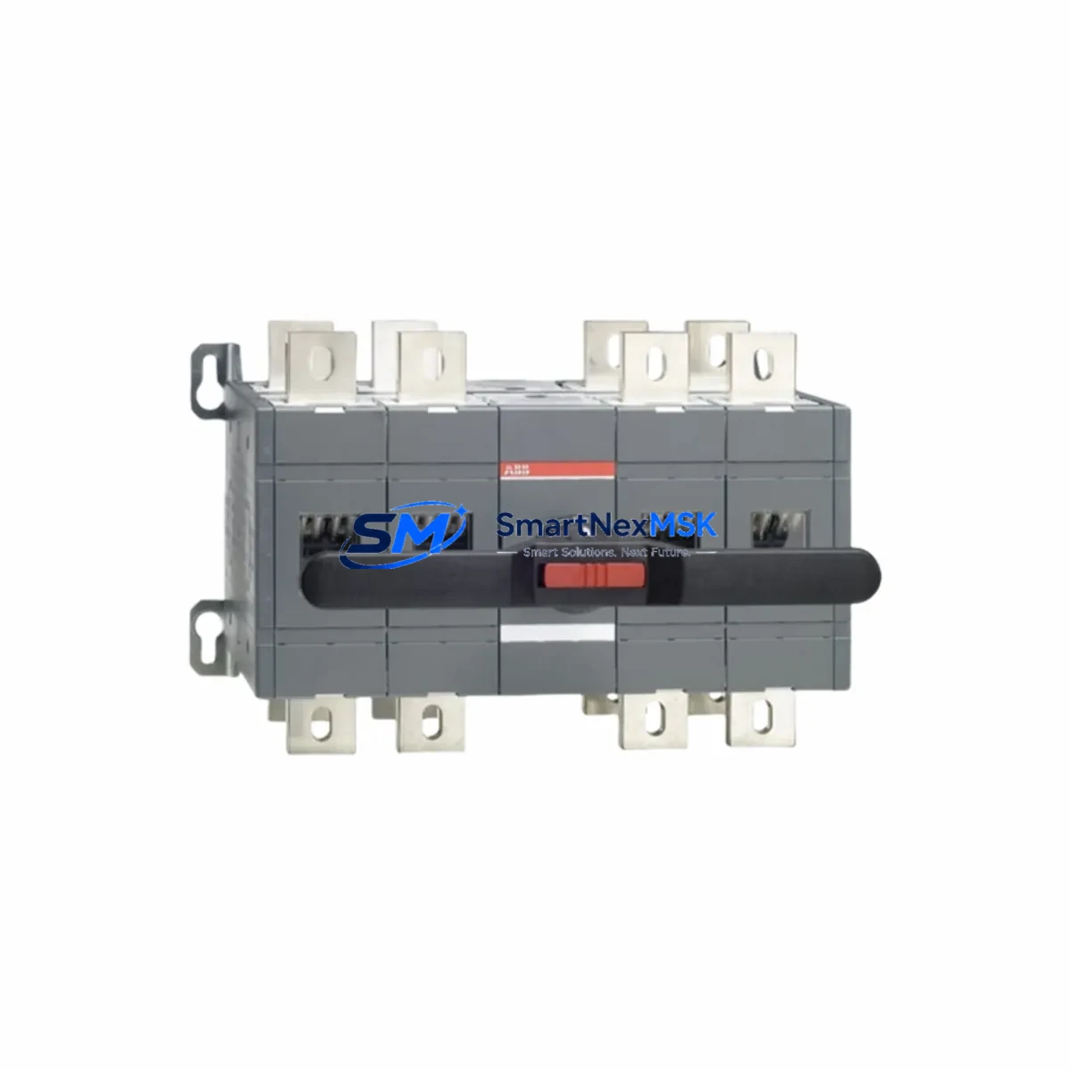
The ABB 1SCA022115R6180 is a 250A, 4-pole switch-disconnector from ABB’s OT Series, engineered for seamless integration into existing industrial control panels, motor control centers (MCCs), and distribution switchgear. As legacy disconnector assemblies reach end-of-life or become unavailable through standard supply chains, the 1SCA022115R6180 serves as a verified retrofit replacement — maintaining electrical compatibility with original wiring layouts, busbar configurations, and enclosure mounting standards without requiring panel redesign.
This unit is manufactured in Germany under ABB’s ISO-certified production standards and carries CE marking for compliance with IEC 60947-3. It is rated for AC-23A duty, making it suitable for switching motor loads, transformer primaries, and capacitor banks in both new installations and brownfield upgrade projects. The 4-pole configuration supports three-phase plus neutral switching, a critical requirement in TN-S and TN-C-S earthing systems where neutral isolation is mandated during maintenance isolation procedures.
Upgrade Compatibility Table
| Parameter | 1SCA022115R6180 (Current) | Retrofit Notes |
|---|---|---|
| Rated Current | 250A | Matches OT250 frame rating; no derating required |
| Poles | 4P (3Ph + N) | Direct replacement for 4-pole legacy disconnectors in TN-S systems |
| Mounting | DIN rail / panel mount | Compatible with standard 250A OT Series enclosure cutouts |
| Terminal Type | Box clamp, top & bottom | Accepts existing cable lugs up to 185mm²; no re-termination needed |
| Busbar Compatibility | OT Series busbar adapters | Compatible with OT250 busbar kits (e.g., OS250D03P busbar adapter) |
| Communication | N/A (manual operation) | Motorized drive OTM250E3M230C can be retrofitted for remote operation |
| Auxiliary Contacts | Optional add-on | OT-series auxiliary contact blocks (e.g., OTPS25F3) snap-fit without tools |
| Replacement Recommendation | Drop-in for OT250 4P variants | Verify handle/shaft alignment if using existing door-coupling mechanism |
| Commissioning Focus | Torque settings, phase sequence | Re-torque terminals to 14 Nm; verify phase rotation with clamp meter |
| Warranty | 12 Months | Covers manufacturing defects; includes pre-shipment functional test |
Retrofit Planning for Existing Automation Systems
Successful integration of the 1SCA022115R6180 into a brownfield control system begins with a thorough audit of the existing panel layout. In most OT Series installations, the disconnector is mounted within a steel enclosure alongside components such as the ABB A-line contactor (e.g., A145-30), thermal overload relay (e.g., TA200DU-200), and upstream fuse base (e.g., OS400D03P with NH fuse links). Before removal of the legacy unit, document all terminal assignments, cable routing, and any interlocking mechanisms connected to the existing disconnector shaft.
Power supply verification is essential. Confirm that the upstream transformer or incomer breaker — often an ABB SACE Tmax T5 or equivalent 250A MCCB — is rated to supply the full 250A continuous load without nuisance tripping during motor starting transients. If the panel includes a soft starter such as the ABB PSR or PSS series, verify that the disconnector’s upstream position does not interfere with the soft starter’s bypass contactor sequencing.
For panels incorporating ABB AC500 or AC31 series PLCs with digital output modules controlling the disconnector’s motorized drive, review the I/O address mapping in the existing PLC program. If the OTM250 motorized operator is being added as part of this retrofit, assign new digital output addresses for the OPEN and CLOSE commands and update the PLC ladder logic or function block diagram accordingly. Ensure that the PLC’s 24VDC power supply module — such as the CP604 or CP605 — has sufficient residual capacity to power the new motorized operator’s control circuit.
Where the existing system uses an ABB Panel Builder or CP600 HMI for operator interface, update the relevant mimic screen to reflect the new disconnector’s status feedback. The auxiliary contact block (OTPS25F3 or similar) provides the 1NO+1NC signal required for HMI position indication. Map these signals to the existing HMI tag database and verify that the “Disconnector Open” and “Disconnector Closed” status indicators function correctly during pre-commissioning loop checks.
In systems where communication is routed via PROFIBUS DP or Modbus RTU — common in older ABB Freelance DCS or AC31 installations — confirm that the addition of any new I/O points does not exceed the master’s configured node count. If I/O expansion is required, an ABB CI840A PROFIBUS adapter or additional S800 I/O modules may be needed to accommodate the new status and control signals without disrupting the existing communication topology.
Downtime Control During System Migration
Minimizing production downtime during a disconnector replacement requires careful pre-staging and a structured isolation procedure. Begin by preparing the 1SCA022115R6180 for installation before the maintenance window opens: verify the unit’s rated current, confirm terminal torque specifications, and pre-fit any auxiliary contact blocks or shaft extensions in the workshop environment. This reduces in-panel assembly time to under 30 minutes for a straightforward swap.
During the isolation window, follow a strict lockout/tagout (LOTO) procedure on the upstream incomer. Use a calibrated clamp meter to confirm zero voltage on all four poles before disconnecting the existing unit. Photograph the original wiring layout — particularly the neutral conductor routing — before removing any terminals. The 1SCA022115R6180’s box clamp terminals accept the same cable cross-sections as the legacy OT250 unit, so existing cable lugs can typically be reused without re-crimping, provided they are within the 16–185mm² acceptance range.
After installation, perform a continuity check across all four poles with the disconnector in the closed position before re-energizing. Re-torque all terminals to the specified 14 Nm and verify that the door-coupling handle (if fitted) operates smoothly through the full ON/OFF arc. On re-energization, monitor the load current on all three phases using a power analyzer to confirm balanced loading and absence of neutral current anomalies. If a motorized drive has been added, test both local and remote OPEN/CLOSE commands before returning the system to automatic control from the PLC or DCS.
Maintaining a spare 1SCA022115R6180 unit on-site as a critical spare is strongly recommended for facilities operating continuous processes. With a 12-month warranty covering manufacturing defects and a pre-shipment functional test included with every unit, procurement lead times can be planned in advance to ensure inventory availability aligns with scheduled maintenance cycles.
Retrofit Support FAQ
Q1: Is the 1SCA022115R6180 a direct drop-in replacement for older ABB OT250 4-pole disconnectors?
Yes. The 1SCA022115R6180 shares the same frame dimensions, terminal positions, and mounting footprint as the OT250 4P series. In most cases, existing cable terminations, busbar adapters, and door-coupling shafts can be reused without modification. Verify the shaft length if a rotary handle or door-coupling kit is installed, as extended shaft variants may require a separate adapter.
Q2: What wiring checks are required before commissioning the replacement unit?
Confirm that all four conductors (L1, L2, L3, N) are correctly assigned to the corresponding terminals on the new unit. Re-torque all terminals to 14 Nm using a calibrated torque wrench. Perform an insulation resistance test at 500VDC between each pole and earth before re-energizing. If auxiliary contacts are fitted, verify the 1NO+1NC signal continuity with a multimeter in the open and closed positions.
Q3: Can this unit be used with a motorized operator for remote switching?
Yes. The ABB OTM250E3M230C motorized operator is compatible with the 1SCA022115R6180 and can be retrofitted to enable remote OPEN/CLOSE control via a 230VAC control signal. This is commonly used in applications where the disconnector is integrated into a SCADA or BMS system. Ensure the control circuit is protected by a dedicated MCB and that the PLC output module’s current rating is sufficient to drive the operator’s coil.
Q4: What does the 12-month warranty cover, and is a pre-shipment test included?
Every 1SCA022115R6180 unit supplied by SMARTNEXMSK undergoes a pre-shipment functional test covering mechanical operation, terminal integrity, and auxiliary contact continuity. The 12-month warranty covers manufacturing defects in materials and workmanship from the date of shipment. It does not cover damage resulting from incorrect installation, overloading beyond rated current, or environmental exposure outside the unit’s IP rating. Warranty claims are processed within 5 business days of receipt of the returned unit.
© 2026 SMARTNEXMSK. All rights reserved.
Original Source: https://smartnexmsk.com
Contact: sales@smartnexmsk.com | +86 18259474341


