ABB 200-APB12 Retrofit-Ready PROFIBUS DP Adapter for ACS800 Control Systems
The ABB 200-APB12 is a PROFIBUS DP fieldbus adapter module designed for seamless integration into ABB ACS800 series variable frequency drives. As legacy automation systems approach end-of-life and spare parts become increasingly difficult to source, the 200-APB12 serves as a critical retrofit component for engineers tasked with modernizing aging drive communication architectures without replacing the entire control cabinet. Whether you are restoring a discontinued drive network, migrating from a proprietary fieldbus to PROFIBUS DP, or expanding I/O capacity across a distributed control system, the 200-APB12 provides a verified, drop-in compatible upgrade path that minimizes engineering risk and reduces unplanned downtime.
This adapter slots directly into the option slot of compatible ACS800 drive units, establishing a PROFIBUS DP slave connection to the master PLC or DCS controller. The module supports standard GSD file-based configuration, enabling integration with Siemens S7-300, S7-400, and S7-1500 series controllers, as well as Schneider Electric Modicon M340 and Premium platforms. Engineers replacing older RDCO-02 or RDCO-03 communication option boards will find the 200-APB12 a functionally equivalent successor, with identical terminal assignments and compatible parameter mapping for ACS800 firmware versions 7.x and above.
Before committing to a retrofit installation, field engineers should verify several critical compatibility parameters. First, confirm the drive’s internal power supply capacity — the option slot draws approximately 200 mA at 5 VDC, and overloaded internal supplies on older ACS800 units can cause intermittent communication faults. Second, review the existing PROFIBUS segment termination: the 200-APB12 requires correct bus termination at both ends of the DP segment, and improperly terminated networks are a leading cause of post-retrofit communication instability. Third, validate the existing PLC program’s node address assignments — the 200-APB12 node address is set via drive parameters (parameter 51.01 in standard ACS800 firmware), and address conflicts with other DP slaves such as ABB RETA-01 Ethernet adapters or RCAN-01 CANopen modules will prevent successful network initialization.
Upgrade Compatibility Table
| Parameter | Details |
|---|---|
| Compatible Drive Series | ABB ACS800 (all frame sizes with option slot) |
| Replaces / Supersedes | RDCO-02, RDCO-03, earlier 200-APB revisions |
| Communication Protocol | PROFIBUS DP (EN 50170 / IEC 61158) |
| Baud Rate Support | 9.6 kbps – 12 Mbps (auto-detect) |
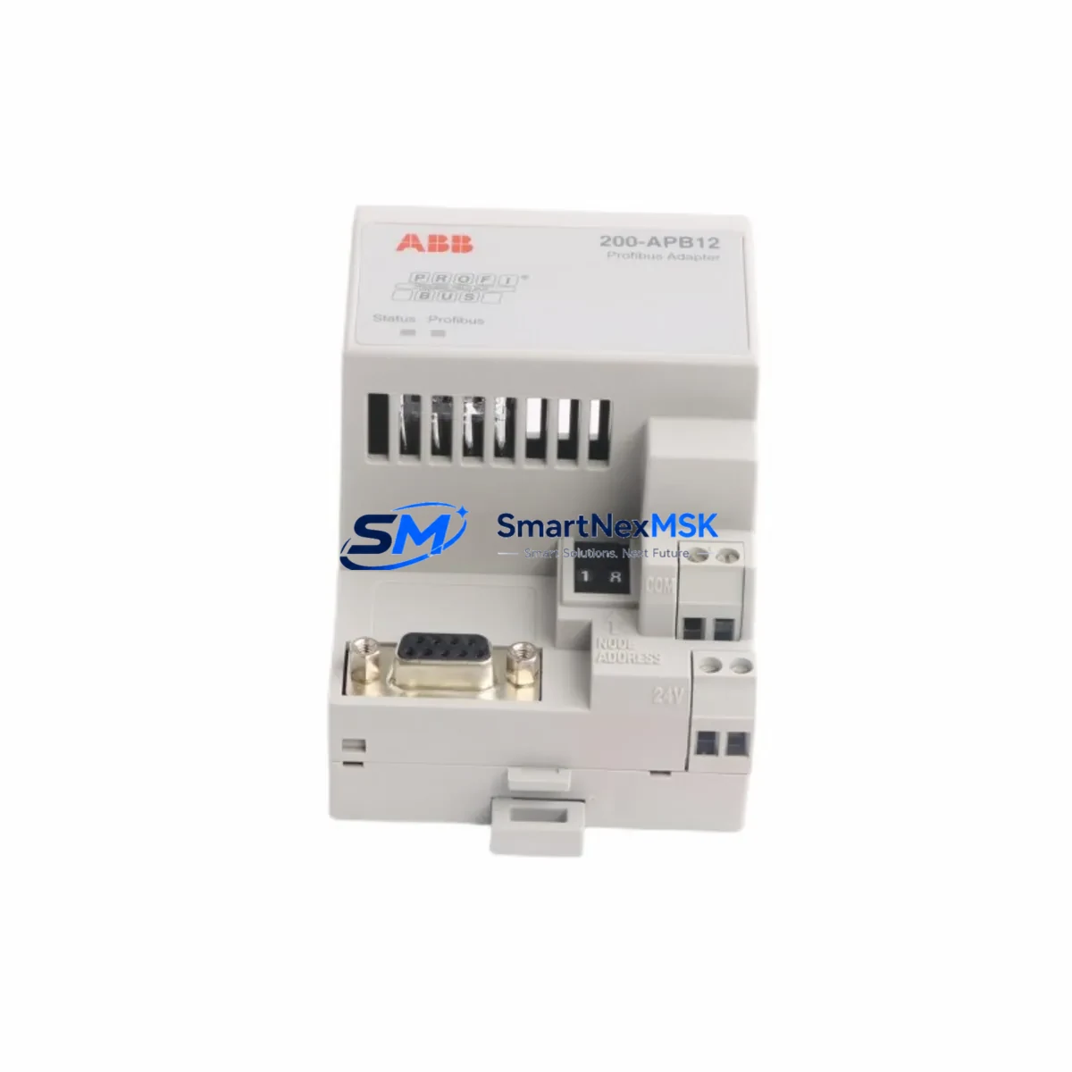
| Installation Interface | ACS800 option slot (D-sub 9-pin DP connector) |
| Node Address Setting | Via drive parameter 51.01 (range 1–125) |
| GSD File | ABB_0812.GSD (compatible with STEP 7, TIA Portal, Unity Pro) |
| Power Consumption | ~200 mA @ 5 VDC (internal drive supply) |
| Retrofit Wiring Change | None required — same D-sub 9-pin pinout as predecessor |
| Commissioning Tool | DriveWindow 2, DriveStudio, or ACS800 keypad (CDP312R) |
| Firmware Compatibility | ACS800 standard firmware 7.x and above |
| Warranty | 12 Months — covers manufacturing defects and communication faults |
Retrofit Planning for Existing Automation Systems
A successful 200-APB12 retrofit begins well before the module arrives on site. Start by auditing the existing control cabinet layout: identify the ACS800 drive frame size, confirm the option slot is unoccupied or document which existing module (such as an RDCO-02 or an older RPBA-01 PROFIBUS adapter) will be removed. If the cabinet also houses an ACS800 application program stored on an RMIO-11 or RMIO-12 main circuit board, back up the full parameter set using DriveWindow 2 before any hardware changes — parameter loss during a module swap is a common and avoidable cause of extended downtime.
For systems where the ACS800 communicates upstream to a Siemens ET 200M distributed I/O rack or a Schneider Quantum backplane, verify that the PROFIBUS DP master’s hardware configuration reflects the correct GSD file for the 200-APB12. Mismatched GSD versions between the adapter and the PLC project are a frequent source of “Module not found” faults during initial power-up. If the existing PLC project was built around an older RPBA-01 GSD, a partial reconfiguration of the DP master station in STEP 7 or TIA Portal will be required — this typically takes 30–60 minutes for an experienced controls engineer.
In multi-drive installations where several ACS800 units share a single PROFIBUS DP segment alongside other devices — such as ABB RETA-01 Ethernet/IP adapters, RCAN-01 CANopen modules, or third-party Danfoss FC-302 drives with PROFIBUS option cards — pay close attention to segment loading. Each additional DP slave increases bus cycle time; for time-critical applications, recalculate the DP cycle time after adding the 200-APB12 to ensure it remains within the PLC’s watchdog tolerance. Also confirm that the PROFIBUS cable (Belden 3079A or equivalent Type A cable) is correctly shielded and grounded at one end only to prevent ground loop interference, which is especially problematic in high-noise environments near large motor starters or variable speed drives.
If the retrofit involves migrating from a legacy DeviceNet or Modbus RTU communication architecture to PROFIBUS DP, additional gateway hardware such as an HMS Anybus Communicator or a Moxa MGate protocol converter may be required to bridge the old and new network segments during the transition period. This phased migration approach allows the plant to maintain production continuity while the new PROFIBUS backbone is commissioned and validated section by section.
Finally, before closing the control cabinet, perform a full I/O checkout: verify that each drive’s speed reference, run/stop command, fault reset, and actual speed feedback signals are correctly mapped in the PLC program. For ACS800 drives using the ABB standard application program, these signals are typically mapped to PROFIBUS PPO Type 2 or PPO Type 5 data sets — confirm the PPO type selection matches the PLC’s hardware configuration to avoid silent data mapping errors that only manifest under specific operating conditions.
Downtime Control During System Migration
Minimizing production downtime during a PROFIBUS DP retrofit requires a structured pre-commissioning strategy. The most effective approach is to pre-configure and bench-test the 200-APB12 before the scheduled maintenance window. Using a laptop with DriveWindow 2 and a temporary ACS800 test drive, set the node address (parameter 51.01), configure the PPO type (parameter 51.02), and verify that the adapter responds correctly on a test PROFIBUS segment. This bench validation typically takes 1–2 hours and eliminates the most common on-site commissioning failures.
During the actual cutover, follow a strict sequence: power down the ACS800 drive, discharge the DC bus (wait a minimum of 5 minutes after power-off), remove the existing communication module, install the 200-APB12, restore power, and verify the adapter’s LED status indicators before reconnecting the PROFIBUS cable. The 200-APB12 features a green PWR LED (steady = power OK), a yellow BUS LED (flashing = DP communication active), and a red ERR LED (steady = configuration fault). A steady red ERR LED after power-up almost always indicates a GSD mismatch or node address conflict — resolve these in the PLC project before proceeding.
To protect the original program logic during migration, export a full parameter backup from the ACS800 using the CDP312R keypad’s parameter copy function or DriveWindow 2’s upload feature. Store this backup file with the project documentation. If the retrofit requires any changes to the ACS800 application program — for example, remapping I/O signals to match the new PROFIBUS PPO data structure — make these changes in a copy of the original program and validate them on the bench drive before deploying to the production machine. This approach ensures that the original control logic can be restored within minutes if unexpected issues arise during the live cutover.
Retrofit Support FAQ
Q1: Is the ABB 200-APB12 a direct drop-in replacement for the RDCO-02 and RDCO-03?
Yes. The 200-APB12 uses the same D-sub 9-pin PROFIBUS connector and installs in the same ACS800 option slot as the RDCO-02 and RDCO-03. No wiring changes are required. However, you will need to update the GSD file in your PLC project if the existing configuration references the older module’s GSD — this is a software-only change that does not affect field wiring.
Q2: What pre-shipment testing is performed on the 200-APB12?
Every unit undergoes functional power-on testing and PROFIBUS DP communication verification before shipment. We confirm that the PWR and BUS LEDs respond correctly, that the module initializes on a live DP segment, and that parameter read/write operations complete without error. A test report is available upon request for quality-critical applications.
Q3: How do I verify wiring and termination after installation?
After installing the 200-APB12 and connecting the PROFIBUS cable, check that bus termination is active at both physical ends of the DP segment (typically via the termination switch on the D-sub 9-pin connector). Use a PROFIBUS tester or the PLC’s diagnostic function to confirm that the 200-APB12 node address appears in the active station list. If the node does not appear, check the cable shield grounding, verify the baud rate setting on the DP master, and confirm that parameter 51.01 in the ACS800 matches the address configured in the PLC hardware project.
Q4: What does the 12-month warranty cover?
The 12-month warranty covers all manufacturing defects, component failures, and communication faults attributable to the module itself under normal operating conditions. It does not cover damage caused by incorrect installation, overvoltage events, or physical mishandling. Warranty claims are processed within 5 business days; replacement units are dispatched via express courier to minimize production impact. Contact sales@smartnexmsk.com with your order number and a description of the fault to initiate a warranty claim.
© 2026 SMARTNEXMSK. All rights reserved.
Original Source: https://smartnexmsk.com
Contact: sales@smartnexmsk.com | +86 18259474341


