ABB 3ADT315100R1001 Retrofit-Ready Power Supply for DCS800 DC Drive Control Systems
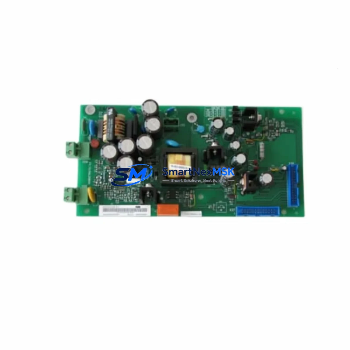
The ABB 3ADT315100R1001, also identified as the SDCS-POW-4-COAT, is an internal power supply board engineered for the ABB DCS800 series DC drive platform. Designed to deliver stable, regulated auxiliary power to the drive’s control electronics, this board is a critical component in maintaining continuous, reliable operation of DC motor control systems across heavy industrial environments including steel mills, paper machines, extruders, winders, and crane drives.
As legacy DCS800 installations age and original spare parts become increasingly scarce, the 3ADT315100R1001 has become one of the most sought-after retrofit and replacement components in the ABB DC drive ecosystem. Whether you are restoring a failed drive, upgrading an aging control cabinet, or building a strategic spare parts inventory, this board provides a verified drop-in solution that eliminates the need for full drive replacement and the associated re-engineering costs.
This unit is supplied fully tested, with conformal coating (COAT variant) for enhanced resistance to humidity, dust, and condensation — a key requirement in harsh industrial environments. Each unit ships with a 12-month warranty covering manufacturing defects and functional performance.
Upgrade Compatibility Table
| Parameter | Details |
|---|---|
| SKU / Part Number | 3ADT315100R1001 |
| Board Designation | SDCS-POW-4-COAT |
| Compatible Drive Series | ABB DCS800 (all frame sizes) |
| Replaces / Supersedes | SDCS-POW-4, SDCS-POW-1, SDCS-POW-2 (earlier revisions) |
| Mounting Interface | DCS800 internal backplane — direct plug-in, no bracket modification |
| Communication Compatibility | Compatible with SDCS-COM-8, SDCS-COM-81 fieldbus adapter boards |
| I/O Compatibility | Works alongside SDCS-IOB-3, SDCS-IOB-41 I/O extension boards |
| Installation Requirement | Drive must be de-energized; verify DC bus discharge before handling |
| Commissioning Tool | DriveWindow Light 2 or DriveStudio via SDCS-COM-8 / USB-to-RS232 cable |
| Conformal Coating | Yes (COAT variant) — suitable for high-humidity and dusty environments |
| Warranty | 12 months from date of shipment |
| Condition | New / Surplus New / Tested Refurbished (specify at order) |
Retrofit Planning for Existing Automation Systems
Replacing the 3ADT315100R1001 in a live production environment requires careful pre-work to avoid extended downtime and configuration loss. Before removing the failed board, engineers should document the existing drive parameters using DriveWindow Light 2 connected via the SDCS-COM-8 fieldbus adapter or a direct RS-232 programming cable. Parameter backup is essential — the DCS800 stores motor data, speed references, torque limits, and PID tuning values that must be restored after the board swap.
On the hardware side, verify that the SDCS-IOB-3 or SDCS-IOB-41 I/O extension boards are seated correctly in the backplane before powering up, as loose connections on these boards can cause false fault codes that mimic power supply failures. Similarly, inspect the SDCS-FEX-2 field excitation board if the application involves a separately excited DC motor — a marginal power supply can cause intermittent field weakening faults that are often misdiagnosed as encoder or speed feedback issues.
For installations where the DCS800 communicates over PROFIBUS-DP or Modbus RTU via the SDCS-COM-81 adapter, confirm that the PLC or DCS master — such as an ABB AC500 controller or a Siemens S7-300 — retains the drive’s node address and baud rate settings in its hardware configuration. After the board replacement, the communication link must be re-established and verified before returning the drive to automatic mode.
In multi-drive cabinets where several DCS800 units share a common DC bus or a coordinated speed reference from an ABB ACS880 master drive, the replaced unit must be re-synchronized to the line speed reference before engaging the load. Failure to do so can cause speed mismatch faults across the drive train. Additionally, if the cabinet includes an ABB NPBA-12 PROFIBUS adapter or an NMBP-01 Modbus Plus module on adjacent drives, verify that the network topology remains intact after the maintenance window.
Terminal wiring on the DCS800 control board uses a standard screw-terminal strip. Cross-reference the existing wiring against the DCS800 Hardware Manual (3ADW000193) before disconnecting any signal wires. Pay particular attention to the analog speed reference input (terminals AI1+/AI1−), the enable signal (terminal DIIL), and the fault relay output (terminals DO1/DO2), as these are the most commonly miswired connections during field replacements.
Downtime Control During System Migration
Minimizing production downtime during a DCS800 power supply board replacement begins with advance preparation. The most effective strategy is to pre-configure a spare 3ADT315100R1001 board off-line before the maintenance window opens. Using a bench test setup with a known-good DCS800 chassis, load the backed-up parameter file and verify that the drive reaches the correct no-load speed reference before the board is transported to the production floor.
On the day of replacement, coordinate with the process control team to ensure the PLC or DCS supervisory system — whether an ABB AC500, a Siemens S7-400, or a Rockwell ControlLogix — is placed in manual hold mode before the drive is isolated. This prevents automatic restart commands from reaching the drive during the swap. Lock out and tag out (LOTO) procedures must be followed, and the DC bus voltage must be confirmed at zero using a calibrated meter before the cabinet is opened.
After the new board is installed and the drive is powered up, perform a static self-test using the drive’s keypad or DriveWindow before connecting the motor. Confirm that all fault codes are cleared, that the field current is within specification, and that the speed feedback signal from the tachometer or encoder is reading correctly. Only then should the drive be returned to remote control mode and the PLC interlock released. This structured approach consistently achieves board replacement and recommissioning within a two-to-four hour window, even in complex multi-drive systems.
Retrofit Support FAQ
Q1: Is the 3ADT315100R1001 a direct drop-in replacement for earlier SDCS-POW variants?
Yes. The SDCS-POW-4-COAT is the current production revision of the DCS800 internal power supply board and is backward compatible with earlier SDCS-POW-1 and SDCS-POW-2 variants. No mechanical modification or firmware change is required for the swap. The board uses the same backplane connector and occupies the same physical slot in all DCS800 frame sizes.
Q2: What commissioning steps are required after installation?
After installing the board and powering up the drive, navigate to parameter group 99 (Start-Up Data) and verify that the motor nominal values — voltage, current, speed, and flux — match the motor nameplate. Run the motor identification routine (ID Run) if the motor data has been lost or if the drive is being paired with a different motor. Confirm fieldbus communication is active and that the PLC is receiving the drive’s status word before releasing the drive to automatic control.
Q3: How do I verify wiring compatibility before powering up?
Compare the existing terminal wiring against the DCS800 Hardware Manual wiring diagram for your specific frame size. Key terminals to verify include the 24 VDC auxiliary supply input, the analog reference inputs (AI1, AI2), the digital inputs (DI1–DI6), the enable input (DIIL), and the fault relay contacts. Use a continuity tester to confirm that no signal wires have been crossed during the replacement. Do not apply power until all terminal connections have been verified.
Q4: What does the 12-month warranty cover?
The 12-month warranty covers manufacturing defects and functional performance failures under normal operating conditions. Each unit undergoes functional testing prior to shipment, including power output verification and insulation resistance checks. Warranty claims are supported by our technical team with a target response time of one business day. Replacement or repair is provided at no charge for confirmed warranty failures within the coverage period.
© 2026 SMARTNEXMSK. All rights reserved.
Original Source: https://smartnexmsk.com
Contact: sales@smartnexmsk.com | +86 18259474341


