ABB 3AUA0000074145 BGDR-01C Spare for ACS800 Automation: Minimize Downtime with Verified IGBT Gate Driver Replacement
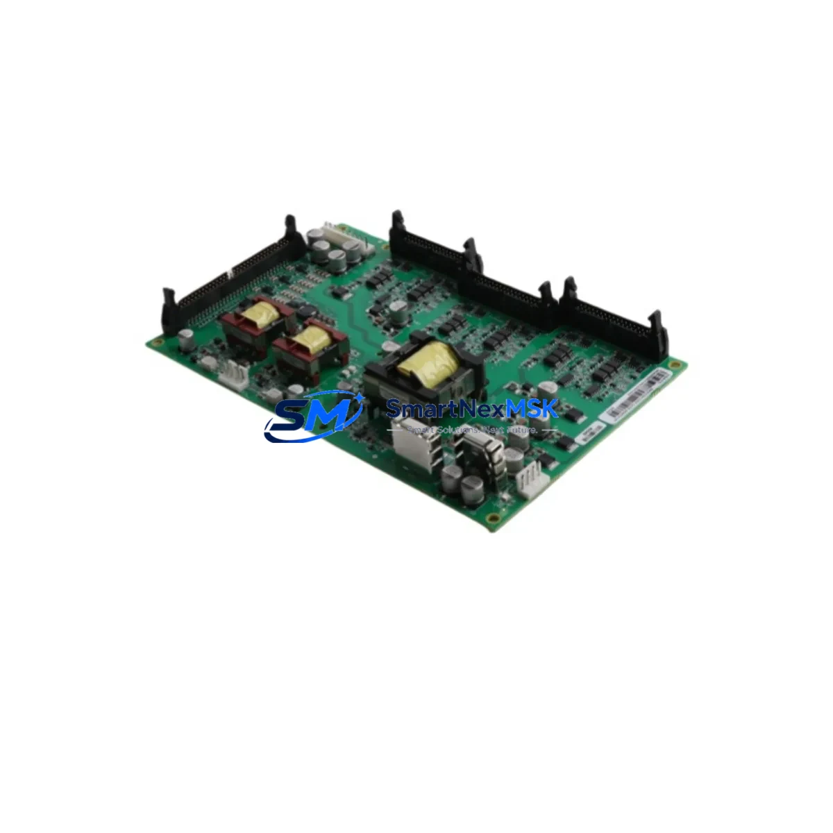
The ABB 3AUA0000074145 / BGDR-01C is an original IGBT Gate Driver Board engineered for the ACS800 series variable frequency drives. In industrial automation environments — from paper mills and metal processing lines to water treatment facilities and heavy-duty conveyor systems — the ACS800 drive platform is a cornerstone of motor control infrastructure. When the BGDR-01C gate driver board fails, the result is immediate drive shutdown, uncontrolled motor coast-down, and unplanned production stoppage. Maintaining a verified spare on-site is the single most effective strategy for rapid downtime recovery.
At SMARTNEXMSK, every 3AUA0000074145 / BGDR-01C unit is sourced from authorized supply channels, subjected to pre-shipment functional testing, and backed by a 12-month warranty. Our inventory is maintained to support both emergency replacement orders and planned maintenance procurement cycles.
Spare Maintenance Table
| Parameter | Specification / Detail |
|---|---|
| Part Number | 3AUA0000074145 |
| Module Reference | BGDR-01C |
| Function | IGBT Gate Driver Board |
| Compatible Series | ABB ACS800 Variable Frequency Drives |
| Drive Frame Sizes | ACS800 R2–R8 (verify frame size against drive nameplate) |
| Nominal Supply Voltage | 24 VDC (internal drive bus) |
| Gate Signal Interface | Fiber optic IGBT trigger signals |
| Mounting | Direct board-level replacement; DIN-rail compatible chassis |
| Operating Temperature | 0°C to +55°C (drive enclosure ambient) |
| Origin | Germany (ABB manufacturing) |
| Condition | Original, new or tested-good surplus |
| Pre-shipment Test | Functional gate signal verification performed |
| Warranty | 12 Months from date of shipment |
| Lead Time | In-stock: ships within 1–3 business days |
| Application Environment | Industrial automation, motor control, process drives |
| Maintenance Recommendation | Inspect fiber optic connectors, gate resistors, and IGBT module condition during replacement |
Maintenance Planning for Continuous Operation
Replacing the BGDR-01C gate driver board is rarely an isolated task. Experienced maintenance engineers understand that a gate driver failure is often symptomatic of broader stress within the drive’s power stage. During a planned or emergency replacement of the 3AUA0000074145, a thorough inspection of the surrounding components is essential to prevent repeat failures and ensure long-term drive reliability.
Begin by examining the IGBT power module (such as the ABB SINT4130C or equivalent frame-matched module) for signs of thermal stress, gate oxide degradation, or collector-emitter leakage. A failed gate driver can mask underlying IGBT damage that will resurface under load. Simultaneously, inspect the DC bus capacitor bank for bulging, electrolyte leakage, or elevated ESR — capacitor degradation is a leading cause of gate driver overvoltage stress.
The AINT board (Auxiliary Interface Board) and RMIO control board should be checked for firmware integrity and communication faults. If the drive has been logging fault codes such as FF-52 (IGBT Overtemperature) or FF-53 (Short Circuit) prior to the gate driver failure, the RMIO board’s fault history should be reviewed and cleared after replacement. The APBU fiber optic branching unit, which distributes gate trigger signals from the RMIO to the BGDR boards, should also be inspected — damaged or contaminated fiber optic cables are a common source of intermittent gate signal errors that can destroy driver boards prematurely.
On the power supply side, verify the SPSU power supply board output voltages (typically +24 VDC, +15 VDC, and ±5 VDC rails) are within specification. An out-of-tolerance supply voltage is a frequent root cause of gate driver board failure. Check the input fuses and DC bus fuses — ABB ACS800 drives use semiconductor fuses rated to the drive’s input current; a blown fuse may indicate a fault condition that preceded the gate driver failure.
For drives with fieldbus communication, inspect the RDCO-01/02/03 DDCS communication module or RPBA-01 PROFIBUS adapter for loose connectors or firmware mismatches that could cause control-level faults misdiagnosed as hardware failures. Finally, review the cooling fan assembly and heatsink thermal interface — inadequate cooling is the primary accelerator of IGBT and gate driver aging in ACS800 drives operating in high-ambient or high-duty-cycle environments.
Maintaining a coordinated spare parts kit — including the BGDR-01C gate driver, SPSU power supply board, RMIO control board, DC bus fuses, and fiber optic patch cables — reduces mean time to repair (MTTR) from hours to minutes and is the foundation of a robust ACS800 maintenance strategy.
Site Replacement Workflow
Step 1 — Isolation & Lockout/Tagout: De-energize the ACS800 drive and apply LOTO procedures. Allow a minimum of 5 minutes for DC bus capacitors to discharge below 50 VDC before opening the drive cabinet. Verify with a calibrated multimeter.
Step 2 — Fault Code Documentation: Before disconnecting any boards, record all active and historical fault codes from the ACS800 panel (CDP or ACS-CP-C control panel) or via DriveWindow software. This data is critical for root cause analysis.
Step 3 — Fiber Optic Disconnection: Carefully disconnect the fiber optic cables from the BGDR-01C board. Label each cable with its connector position. Fiber optic connectors are sensitive — avoid bending cables beyond their minimum bend radius and protect connector faces from contamination.
Step 4 — Board Removal & Inspection: Remove the faulty 3AUA0000074145 board. Inspect the mounting standoffs, PCB traces, and gate resistors for burn marks or mechanical damage. If damage extends to the IGBT module or bus bars, escalate to a full power stage inspection before installing the replacement.
Step 5 — Replacement Installation: Install the new BGDR-01C board, reconnect fiber optic cables in the correct sequence, and verify all connectors are fully seated. Restore power and perform a no-load test run, monitoring for fault codes before returning the drive to full production load.
Step 6 — System Verification: Confirm motor current, output frequency, and drive temperature readings are within normal operating parameters. Log the replacement in the site maintenance record with the new board’s serial number and warranty start date.
This workflow is compatible with direct replacement of legacy BGDR-01B boards in earlier ACS800 frame variants — always verify the part number suffix against the drive’s internal wiring diagram before installation.
Spare Parts Support FAQ
Q1: Is the 3AUA0000074145 / BGDR-01C compatible with all ACS800 drive frame sizes?
The BGDR-01C is designed for specific ACS800 frame sizes (typically R4–R8). Compatibility depends on the drive’s power rating and internal configuration. Always cross-reference the part number against the drive’s internal spare parts list or the ABB ACS800 Hardware Manual before ordering. Our technical team can assist with frame-size verification if you provide your drive’s full nameplate data.
Q2: What pre-shipment testing is performed on each unit?
Every 3AUA0000074145 / BGDR-01C shipped from SMARTNEXMSK undergoes functional gate signal verification and visual inspection for PCB damage, component integrity, and connector condition. Units that do not pass inspection are not shipped. A test report is available upon request for critical applications.
Q3: How should I manage BGDR-01C inventory for a multi-drive facility?
For facilities operating 3 or more ACS800 drives, we recommend maintaining a minimum of one BGDR-01C spare per 5 drives, with at least one unit always in stock. For critical production lines with no redundant drive, a dedicated on-site spare is strongly advised. SMARTNEXMSK offers volume pricing and reserved-stock agreements for facilities with ongoing maintenance programs.
Q4: What does the 12-month warranty cover?
The 12-month warranty covers manufacturing defects and functional failures under normal operating conditions from the date of shipment. It does not cover damage resulting from incorrect installation, overvoltage events, or operation outside the drive’s rated parameters. In the event of a warranty claim, SMARTNEXMSK will provide a replacement unit or full refund after fault verification. Contact sales@smartnexmsk.com to initiate a warranty claim.
© 2026 SMARTNEXMSK. All rights reserved.
Original Source: https://smartnexmsk.com
Contact: sales@smartnexmsk.com | +86 18259474341


