ABB 3BHE003855R0001 Retrofit-Ready Excitation Interface Board for UNS2882A Series Control Systems
The ABB 3BHE003855R0001 (UNS2882A-P, V1) is a high-reliability excitation interface board engineered for ABB’s AC800M distributed control system platform. As legacy excitation control architectures reach end-of-life, this module serves as the definitive retrofit-ready replacement for facilities operating aging UNS2882A-series excitation controllers. Whether your plant is executing a full DCS modernization, recovering from an unplanned module failure, or upgrading a control cabinet to meet current safety and communication standards, the 3BHE003855R0001 provides a verified drop-in solution with minimal re-engineering overhead.
Sourced from authorized distribution channels and subject to full functional testing prior to shipment, each unit is backed by a 12-month warranty covering manufacturing defects and operational failures under normal industrial service conditions. Stock is maintained to support urgent replacement scenarios, with expedited dispatch available for critical production environments.
Upgrade Compatibility Table
| Parameter | Details |
|---|---|
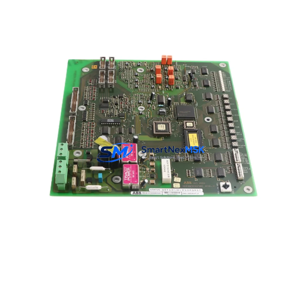
| Part Number | 3BHE003855R0001 |
| Module Designation | UNS2882A-P, V1 |
| Compatible Platform | ABB AC800M DCS, Symphony Plus, Advant OCS |
| Replaces / Supersedes | UNS2882A legacy excitation interface variants |
| Backplane Interface | ABB S800 I/O bus; standard rack-mount slot |
| Communication Compatibility | PROFIBUS-DP, ModuleBus, MasterBus 300 |
| Power Supply Requirement | 24 VDC nominal; verify cabinet PSU capacity before installation |
| Terminal Wiring | Compatible with existing UNS2882A field wiring; confirm terminal block pitch |
| Module Address Configuration | DIP switch or software-assigned; must match original node address in AC800M project |
| Firmware / Software | Compatible with Control Builder M; no firmware re-flash required in most cases |
| Installation Requirement | Standard DIN rail or rack slot; no mechanical modification required |
| Retrofit Recommendation | Direct replacement; verify I/O channel mapping in existing PLC program |
| Commissioning Focus | Excitation loop calibration, HMI tag re-binding, communication link verification |
| Warranty | 12 months from shipment date |
Retrofit Planning for Existing Automation Systems
Successful integration of the 3BHE003855R0001 into an existing control architecture requires systematic pre-installation planning. Begin by auditing the power budget of the existing control cabinet: the 24 VDC bus supplying the backplane must have sufficient headroom to support the replacement module alongside co-installed components such as the PM864A process controller, AI810 analog input modules, AO810V2 analog output modules, and any active communication adapters like the CI854A PROFIBUS interface module. Overloaded power rails are a leading cause of intermittent faults during post-retrofit commissioning.
Terminal wiring from the field side — including excitation feedback signals, generator AVR control lines, and protective relay interfaces — should be documented and photographed before removal of the legacy board. The UNS2882A-P terminal layout is consistent with earlier UNS2882A variants, but engineers should verify conductor cross-sections and ferrule types against the updated terminal block specifications. Where the original installation used unmarked or color-coded wiring without formal documentation, a point-to-point continuity check is mandatory before energization.
Backplane slot assignment must be confirmed against the AC800M hardware configuration stored in the Control Builder M project file. The replacement module must occupy the same physical slot as the original to preserve the I/O channel-to-tag mapping. If the slot position has changed due to rack reconfiguration — for example, following the addition of a DP820 PROFIBUS slave adapter or a TB820V2 ModuleBus modem — the hardware configuration must be updated and re-downloaded to the PM864A controller before the new module is powered on.
For sites running Symphony Plus or Advant OCS alongside AC800M, confirm that the excitation interface signals are correctly mapped in the cross-platform communication layer. MasterBus 300 links between legacy Advant controllers and the AC800M segment must remain intact during the swap to avoid loss of supervisory control. Where PROFIBUS-DP is used as the field communication backbone, verify that the GSD file for the replacement module matches the configured slave profile in the PROFIBUS master — typically the CI854A or CI855 communication interface.
HMI screens built on ABB’s 800xA or older Operate IT environment should be reviewed for tag references tied to the excitation interface. Faceplates displaying excitation current, field voltage, and AVR mode status must be validated against the new module’s signal list. In many retrofit projects, HMI re-binding accounts for a significant portion of commissioning time and should be allocated accordingly in the project schedule.
Downtime Control During System Migration
Minimizing production downtime during excitation interface replacement requires a structured hot-swap protocol where plant safety systems permit. Prior to shutdown, export and archive the full AC800M project from Control Builder M, including all function block diagrams, SFC sequences, and hardware configuration files. This backup serves as the recovery baseline if commissioning reveals unexpected compatibility issues.
Where a parallel test rack is available — populated with a spare PM864A controller, the replacement 3BHE003855R0001 module, and representative I/O such as DI810 digital input and DO810 digital output modules — pre-commissioning validation can be completed offline. Simulate the excitation control loop using a signal generator connected to the module’s analog inputs, and verify that the controller executes the AVR control algorithm correctly before the unit is installed in the live cabinet.
During the live cutover, coordinate with the electrical team to place the generator in manual excitation mode, isolating the AVR loop from the DCS. This preserves field control continuity while the interface board is swapped. After physical installation and wiring verification, restore the hardware configuration download to the PM864A, confirm module status LEDs indicate healthy communication on the ModuleBus, and gradually transfer AVR control back to automatic mode under close observation. Total controlled downtime for a prepared team typically ranges from 45 minutes to 2 hours, depending on cabinet access and wiring complexity.
All replaced modules — including the legacy UNS2882A-P board and any associated SA801F signal adapter or TB807 terminal base — should be retained and labeled for a minimum of 30 days post-commissioning as a contingency spare, in the event that field conditions reveal an unforeseen incompatibility requiring rollback.
Retrofit Support FAQ
Q1: Is the 3BHE003855R0001 a direct replacement for all UNS2882A variants?
The 3BHE003855R0001 (UNS2882A-P, V1) is the current production revision of the UNS2882A excitation interface board and is compatible with the majority of UNS2882A-series installations. However, early-revision UNS2882A units installed in Advant OCS racks prior to 2005 may use a different backplane connector pitch. Confirm the rack generation and hardware revision before ordering. Our technical team can assist with cross-reference verification based on your existing module’s nameplate data.
Q2: What commissioning steps are required after installation?
After physical installation, the following commissioning sequence is recommended: (1) verify module address matches the AC800M hardware configuration; (2) confirm 24 VDC supply voltage at the backplane connector; (3) download the hardware configuration from Control Builder M and confirm the module appears online; (4) perform an excitation loop functional test with the generator offline; (5) validate HMI tag bindings for excitation current and field voltage displays; (6) restore automatic AVR control and monitor for alarm-free operation over a minimum 30-minute observation period.
Q3: Does the module ship pre-tested, and what does the 12-month warranty cover?
Yes. Every 3BHE003855R0001 unit undergoes functional testing prior to shipment, including power-on self-test, communication interface verification, and I/O channel continuity checks. The 12-month warranty covers manufacturing defects and component failures under normal operating conditions (24 VDC supply, ambient temperature within rated range, no physical damage). Warranty claims are supported by our technical team with replacement dispatch typically within 3 business days.
Q4: Can the original field wiring be reused without modification?
In most cases, yes. The UNS2882A-P terminal layout is consistent across revisions, and existing field cables connected to the TB807 terminal base or SA801F signal adapter can typically be reused without re-termination. However, if the original installation used non-standard cable routing or if the terminal base itself shows signs of wear or corrosion, replacement of the terminal base is recommended as part of the retrofit to ensure long-term connection integrity. Always perform a wiring continuity and insulation resistance test before energizing the replacement module.
© 2026 SMARTNEXMSK. All rights reserved.
Original Source: https://smartnexmsk.com
Contact: sales@smartnexmsk.com | +86 18259474341


