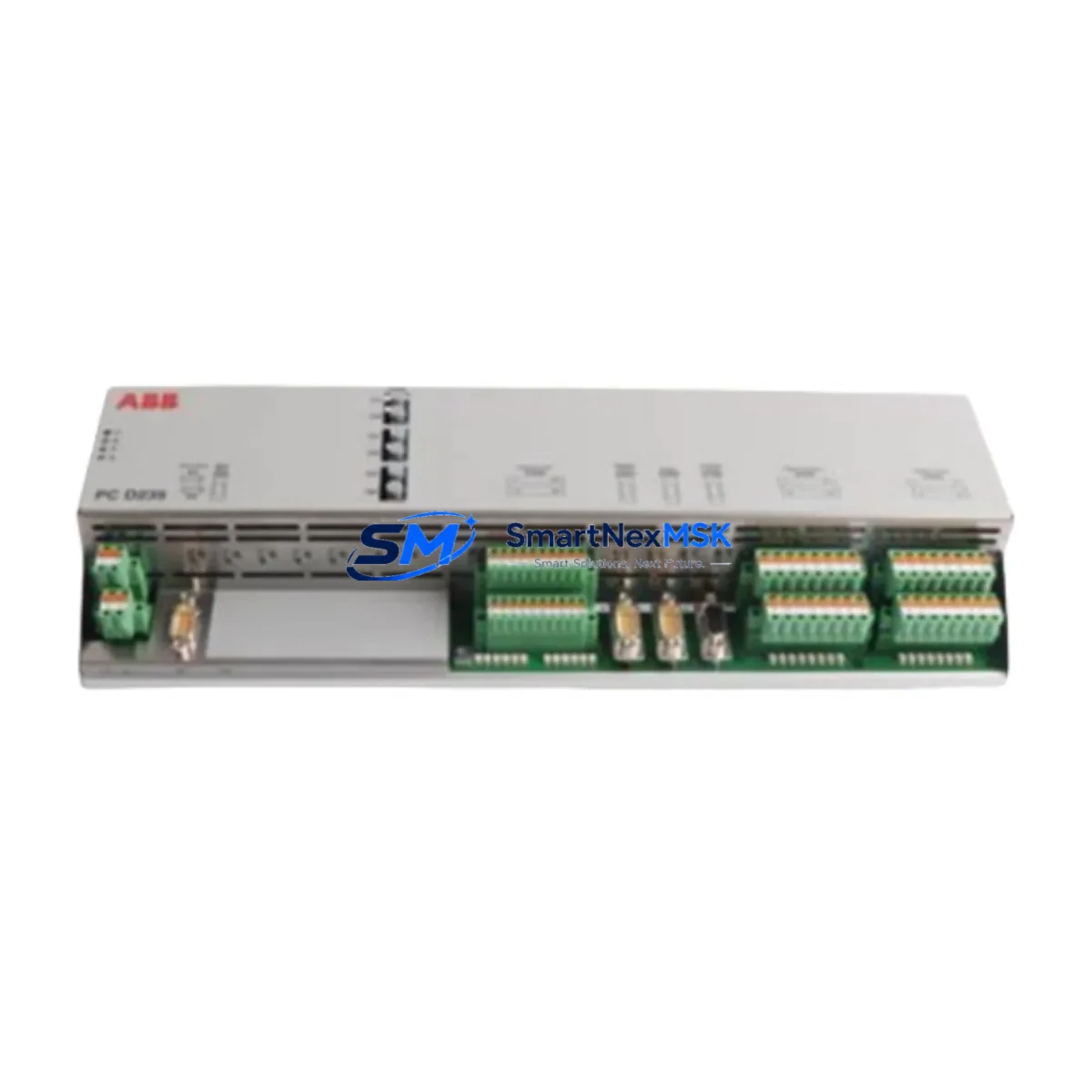
ABB 3BHE022294R0101 Retrofit-Ready Analog Input Module for ACS800 & DCS800 Control Systems
The ABB 3BHE022294R0101 (also identified as GFD233 A) is a high-precision analog input module engineered for seamless integration into ABB’s ACS800 and DCS800 drive control platforms. As legacy automation infrastructure ages and OEM support windows close, this module has become a critical retrofit component for engineers tasked with modernizing existing control cabinets without full system replacement. Whether you are managing a planned upgrade cycle or responding to an unplanned failure of a discontinued board, the 3BHE022294R0101 provides a verified, drop-in compatible solution that preserves your existing program logic, wiring topology, and HMI screen configurations.
Sourced directly from authorized distribution channels and subjected to full functional testing prior to shipment, each unit is backed by a 12-month warranty covering manufacturing defects and operational failures under normal industrial conditions. Stock is maintained on-hand to support urgent dispatch requirements, minimizing unplanned downtime for production-critical installations.
Upgrade Compatibility Table
| Parameter | Details |
|---|---|
| SKU / Part Number | 3BHE022294R0101 (GFD233 A) |
| Compatible Platforms | ABB ACS800, DCS800 series drive control systems |
| Module Function | Analog Input — signal conditioning and process variable acquisition |
| Backplane Interface | ABB RDCO / RDNA compatible rack backplane connector |
| Communication Compatibility | DDCS (Distributed Drive Control System) fiber-optic link; compatible with PROFIBUS-DP via RPBA-01 adapter |
| Terminal Wiring | Screw-terminal block; pin-for-pin compatible with original GFD233 A footprint |
| Installation Requirement | DIN rail or panel-mount rack; no mechanical modification required |
| Replacement Recommendation | Direct replacement for discontinued GFD233 A boards in ACS800 and DCS800 cabinets |
| Commissioning Notes | Module address must be verified in DriveWindow or DriveStudio before power-on; parameter group 98 (AI configuration) should be reviewed |
| Warranty | 12 months from date of shipment; covers manufacturing defects and functional failures |
Retrofit Planning for Existing Automation Systems
Successful integration of the ABB 3BHE022294R0101 into a running production environment requires methodical pre-installation planning. Before removing the failed or obsolete board, engineers should document the existing terminal wiring layout using the cabinet’s as-built drawings, cross-referencing each signal wire against the ACS800 or DCS800 I/O parameter map. The module slots into the same rack position as the original GFD233 A, sharing the same backplane bus architecture used across the ACS800 drive family.
Power supply capacity is a frequent oversight in retrofit projects. The APOW-01 or APOW-02 power supply module feeding the control rack must be verified to have sufficient headroom for the replacement analog input board, particularly in cabinets where additional I/O expansion modules such as the AIMA-01 analog I/O extension or AITC-01 thermocouple input module have been added over the system’s service life. Overloading the rack power bus is a common cause of intermittent faults after module replacement.
Communication link integrity must also be confirmed. In ACS800 multi-drive configurations, the DDCS fiber-optic ring connecting the master drive to follower units passes through the control board stack. If the system uses a RDCO-02 or RDCO-04 DDCS communication module, the fiber connections to and from the replaced board should be inspected for contamination or bend-radius violations before recommissioning. For installations using PROFIBUS-DP fieldbus, the RPBA-01 adapter module address and baud rate settings must be preserved from the original configuration.
HMI screen compatibility is another consideration. Facilities running ABB Panel Builder or third-party SCADA systems mapped to ACS800 parameter addresses will find that the 3BHE022294R0101 maintains the same parameter structure, meaning existing HMI graphics, alarm setpoints, and trend historian tags remain valid without screen redesign. This is a significant advantage over cross-brand migration paths that require full HMI re-engineering.
For systems incorporating the RTAC-01 or RTAC-02 pulse encoder interface module alongside analog inputs, the module address assignment in the drive’s parameter group must be re-verified after board swap to prevent address conflicts on the internal I/O bus. Similarly, if the cabinet includes an RDNA-01 DeviceNet adapter or an RCAN-01 CANopen module for higher-level network integration, the network node address and EDS file configuration should be confirmed unchanged before returning the drive to automatic mode.
Facilities managing multi-axis or coordinated motion systems built on the ACS800-07 or DCS800 regenerative DC drive platform should also audit the SDCS-CON-4 control board and SDCS-IOB-3 I/O board configurations in adjacent cabinets to ensure the analog reference signals feeding the replaced module are within the expected voltage or current range after the swap.
Downtime Control During System Migration
Minimizing production interruption during an analog input module replacement on an ACS800 or DCS800 system begins with a structured pre-outage checklist. Before initiating the controlled shutdown, use DriveWindow Light or DriveStudio to perform a full parameter backup of the drive, saving the dataset to both a local PC and a removable storage device. This backup captures all parameter groups including the AI scaling factors, filter time constants, and fault response configurations that are specific to your process — data that cannot be recovered from a factory reset.
During the physical swap, the drive’s main contactor should be opened and the DC bus voltage confirmed below 50 V using a calibrated meter before any board handling begins. The 3BHE022294R0101 is a static-sensitive assembly; ESD precautions including wrist straps and anti-static mat usage are mandatory. The module’s edge connector should be inspected for bent pins or contamination before seating it into the backplane.
After installation, restore the parameter backup via DriveWindow before energizing the control supply. Perform a dry-run test with the motor disconnected to verify that all analog input channels are reading correctly against known reference signals — a 4–20 mA loop calibrator or a precision voltage source is the appropriate tool for this step. Confirm that the drive’s ready signal is asserted and that no fault codes related to AI hardware (fault codes 0x2310 or 0x2320 in ACS800 firmware) are active before reconnecting the load.
For critical continuous-process applications where even a brief interruption is unacceptable, a hot-standby strategy using a pre-configured spare drive with the 3BHE022294R0101 already installed and parameterized can reduce switchover time to under 15 minutes, preserving process continuity while the primary cabinet is serviced.
Retrofit Support FAQ
Q1: Is the 3BHE022294R0101 a direct drop-in replacement for the original GFD233 A board in my ACS800 cabinet?
Yes. The 3BHE022294R0101 is the current production equivalent of the GFD233 A analog input module. It uses the same backplane connector, terminal block layout, and parameter addressing as the original board. No mechanical modification or parameter re-mapping is required for a like-for-like replacement in ACS800 and DCS800 control racks.
Q2: What commissioning steps are required after installing the replacement module?
After physical installation, restore your saved parameter backup using DriveWindow or DriveStudio. Verify the module address in parameter group 98 (Analog I/O configuration). Test each analog input channel against a known reference signal before reconnecting the process load. Check for active fault codes and confirm the drive’s ready status before returning to automatic operation.
Q3: Will my existing PROFIBUS-DP or DDCS network configuration be affected by the module swap?
No, provided the RPBA-01 PROFIBUS adapter or RDCO DDCS module is not disturbed during the replacement. The 3BHE022294R0101 does not alter the drive’s fieldbus node address or communication parameters. However, it is good practice to verify network communication status from the PLC or DCS master after recommissioning to confirm all cyclic data exchanges are intact.
Q4: What does the 12-month warranty cover, and what is the process for a warranty claim?
The 12-month warranty covers manufacturing defects and functional failures under normal industrial operating conditions from the date of shipment. Units that fail within the warranty period should be returned with a description of the fault symptom and the operating environment. Replacement or repair will be arranged within the agreed lead time. Contact sales@smartnexmsk.com or call +86 18259474341 to initiate a warranty claim.
© 2026 SMARTNEXMSK. All rights reserved.
Original Source: https://smartnexmsk.com
Contact: sales@smartnexmsk.com | +86 18259474341


