ABB 3BHE024747R0101 Maintenance-Ready Spare ACS800: Spare Replacement & Industrial Downtime Risk Control
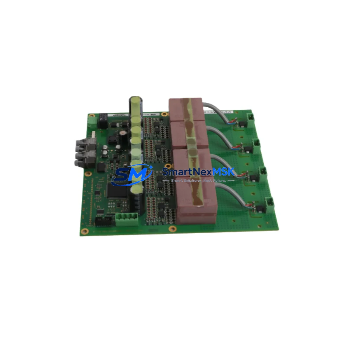
The ABB 3BHE024747R0101 is an original analog output module designed for the ABB ACS800 series variable frequency drive platform — one of the most widely deployed drive systems in heavy industrial, process, and energy automation environments. When this module fails or degrades, the consequences extend far beyond a single signal channel: the entire drive control loop can be compromised, triggering unplanned shutdowns, process deviations, and costly production losses. Maintaining a verified, tested spare of the 3BHE024747R0101 in your site inventory is a fundamental element of any responsible maintenance strategy for ACS800-based systems.
At SMARTNEXMSK, every 3BHE024747R0101 unit is sourced as an original ABB component, subjected to pre-shipment functional verification, and backed by a 12-month warranty. We support maintenance engineers and procurement teams across manufacturing, oil & gas, power generation, water treatment, and marine industries who require fast, reliable access to ACS800 spare parts with full traceability and documented compatibility.
Spare Maintenance Table
| Parameter | Specification / Detail |
|---|---|
| Part Number / SKU | 3BHE024747R0101 |
| Manufacturer | ABB |
| Compatible Series | ACS800 Variable Frequency Drive Series |
| Module Type | Analog Output Module |
| Output Channels | Analog output (current/voltage signal, series-dependent configuration) |
| Signal Type | 4–20 mA / 0–10 V (standard ACS800 analog output range) |
| Installation | Direct board-level replacement; compatible with ACS800 drive control section |
| Origin | Germany (ABB manufacturing) |
| Condition | Original New / Tested Surplus |
| Application Environment | Industrial automation, process control, variable speed drive systems |
| Operating Temperature | 0°C to +55°C (standard ACS800 operating range) |
| Maintenance Recommendation | Inspect signal integrity and connector condition during scheduled drive maintenance; replace if output deviation exceeds ±1% of full scale |
| Warranty | 12 Months — covers functional failure under normal operating conditions |
| Lead Time | In stock — ships within 1–3 business days |
| Shipping | Worldwide; EMS, DHL, FedEx available |
Maintenance Planning for Continuous Operation
Replacing the 3BHE024747R0101 analog output module is rarely an isolated task. In a well-structured ACS800 drive cabinet inspection, maintenance engineers should treat this replacement as an opportunity to audit the entire signal and power chain. Begin by verifying the integrity of the SDCS-CON-4 or RDCO-02 communication adapter boards, which coordinate drive control signals and are subject to the same thermal and vibration stresses as the analog output module. If the drive has been in service for more than five years, the AINT-02 or AINT-14 inverter control boards should also be inspected for capacitor aging and solder joint fatigue.
On the power supply side, confirm that the 24 VDC auxiliary power supply feeding the control section is within tolerance — a marginal power supply is a common root cause of intermittent analog output errors that are misdiagnosed as module failure. Check the APBU-44C or APBU-12C pulse encoder interface units if the drive is operating in closed-loop speed control mode, as encoder signal degradation can mask analog output faults in drive diagnostics.
At the I/O and field wiring level, inspect the terminal blocks and shielded signal cables connected to the analog output channels. Corroded terminals, loose ferrules, or damaged cable shielding can introduce noise that mimics module failure. If the ACS800 system includes an RDIO-01 digital I/O extension module or an RAIO-01 analog I/O extension module, verify their connector seating and firmware compatibility with the current drive software version.
For systems integrated with a DCS or SCADA platform via PROFIBUS or Modbus, the RPBA-01 PROFIBUS adapter or RMBA-01 Modbus adapter should be checked for communication timeout errors that may have been triggered by the analog output fault. Signal isolators between the drive analog outputs and the DCS analog input cards are also worth inspecting — a failed isolator can cause the same symptom as a failed 3BHE024747R0101 module and is often overlooked during fault isolation. Finally, review the drive’s fault log and parameter backup before replacing the module to ensure configuration data is preserved and can be restored after the swap.
Site Replacement Workflow
Step 1 — Pre-Replacement Preparation: Download and archive the current ACS800 parameter set using DriveWindow or DriveStudio software before any hardware intervention. Confirm the replacement 3BHE024747R0101 part number and revision match the installed unit. Verify that the drive firmware version is compatible with the replacement module.
Step 2 — Safe Isolation: Follow ACS800 lockout/tagout procedures. Discharge DC bus capacitors and confirm zero voltage before opening the drive cabinet. Use appropriate PPE for the voltage class of the installation.
Step 3 — Module Removal: Document connector positions and cable routing with photographs before disconnecting. Remove the analog output module by releasing the board retaining clips and carefully extracting the PCB from its slot. Inspect the vacated slot for debris, corrosion, or damaged connector pins.
Step 4 — Installation of 3BHE024747R0101: Insert the replacement module firmly into the correct slot, ensuring all connector pins are fully engaged. Reconnect signal cables in the documented order. Verify that no cables are pinched or under mechanical stress.
Step 5 — Commissioning and Verification: Restore the parameter set from backup. Power up the drive in local control mode and verify analog output signal levels against the process reference. Confirm that the DCS or PLC is receiving correct values on all analog output channels before returning the drive to automatic operation.
This structured replacement workflow minimizes downtime, eliminates configuration errors, and ensures the ACS800 system returns to full operational status with verified performance — typically achievable within a single maintenance shift when a pre-tested spare is available on site.
Spare Parts Support FAQ
Q1: How do I confirm the 3BHE024747R0101 is compatible with my specific ACS800 drive variant?
The 3BHE024747R0101 is designed for the ACS800 series analog output function. Compatibility depends on your drive’s hardware revision and software version. Please provide your drive’s type code and firmware version when contacting us — our technical team will confirm compatibility before shipment. We recommend cross-referencing the ABB ACS800 hardware manual for your specific drive frame size.
Q2: What pre-shipment testing is performed on each unit?
Every 3BHE024747R0101 unit shipped by SMARTNEXMSK undergoes functional verification including power-on testing, analog output signal level checks, and connector integrity inspection. Units are packed in anti-static packaging with individual test records. A 12-month warranty covers functional failure under normal operating conditions from the date of shipment.
Q3: Can I use this module to replace an older revision of the same part number?
In most cases, yes — ABB maintains backward compatibility within the 3BHE024747R0101 product family across hardware revisions. However, we recommend verifying the revision suffix against your drive’s bill of materials or contacting our team for confirmation, particularly for drives running legacy firmware versions that may not support the latest hardware revision.
Q4: What is your recommended spare parts inventory strategy for ACS800 systems?
For critical production lines with ACS800 drives, we recommend maintaining at minimum one spare 3BHE024747R0101 analog output module per drive type in your site inventory, alongside spares for the SDCS-CON-4 control board, AINT-02 inverter control board, and the 24 VDC auxiliary power supply unit. For multi-drive installations, a shared pool of two to three units per module type provides adequate coverage for most unplanned failure scenarios while minimizing capital tied up in spare parts inventory.
© 2026 SMARTNEXMSK. All rights reserved.
Original Source: https://smartnexmsk.com
Contact: sales@smartnexmsk.com | +86 18259474341


