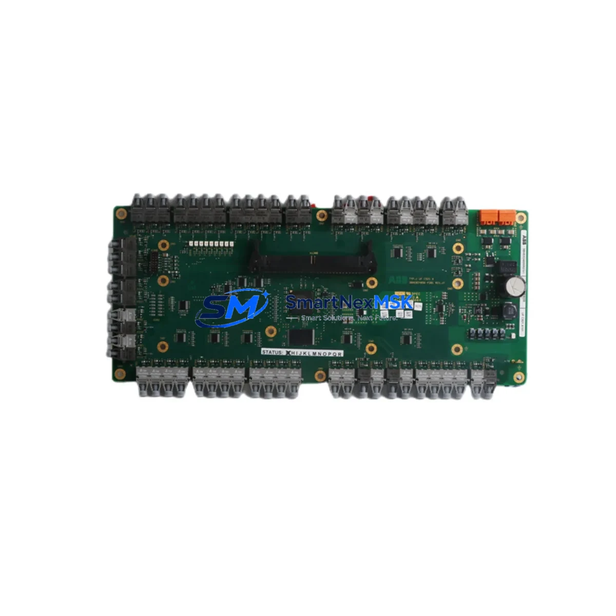
ABB 3BHE024855R0101 UFC921A101 Retrofit-Ready IGBT Control Board for ACS800 / ACS1000 Control Systems
The ABB 3BHE024855R0101 UFC921A101 is a high-reliability IGBT inverter control board engineered for direct retrofit and drop-in replacement within ABB ACS800 and ACS1000 series variable-speed drive systems. As legacy ACS800 units approach end-of-service life and original spare parts become increasingly scarce, the UFC921A101 provides a verified, field-tested upgrade path that preserves existing control architecture, minimizes rewiring, and eliminates the need for full drive replacement. This board is a critical component in modernizing aging automation infrastructure across heavy industry, process manufacturing, marine propulsion, and utility power applications.
The UFC921A101 interfaces directly with the ACS800 and ACS1000 inverter power stages, managing IGBT gate drive signals, fault detection, and real-time current feedback. Its onboard logic is fully compatible with the RDCU-02C and RDCU-12C drive control units, and it communicates via the standard DDCS fiber-optic link used throughout the ACS800 platform. Engineers replacing a failed or degraded UFC921A101 can expect a straightforward swap without firmware re-flashing in most standard configurations, provided the RMIO-11C or RMIO-12C I/O board and the AINT-02C or AINT-12C inverter interface board remain in service.
Upgrade Compatibility Table
| Parameter | Details |
|---|---|
| Compatible Drive Series | ABB ACS800, ACS1000 |
| Replaced / Superseded Part | 3BHE024855R0101 (original OEM), UFC921A101 (functional equivalent) |
| Interface / Backplane | DDCS fiber-optic link; standard ACS800 inverter backplane connector |
| Compatible Control Units | RDCU-02C, RDCU-12C, RMIO-11C, RMIO-12C |
| Compatible Interface Boards | AINT-02C, AINT-12C |
| Communication Protocol | DDCS (Distributed Drive Control System) fiber-optic |
| Installation Requirement | Standard ACS800/ACS1000 inverter module slot; no mechanical modification required |
| Commissioning Notes | Verify IGBT gate timing parameters via DriveWindow or DriveStudio; confirm fault log clear after swap |
| Firmware Compatibility | Compatible with standard ACS800 application firmware; verify version with RDCU control unit |
| Warranty | 12-Month Warranty — covers manufacturing defects and functional failure under normal operating conditions |
Retrofit Planning for Existing Automation Systems
A successful retrofit of the UFC921A101 begins well before the board arrives on site. Engineers should start by auditing the existing ACS800 or ACS1000 drive cabinet to confirm the condition of adjacent components. The APBU-44C branching unit, which distributes DDCS signals to multiple inverter modules in parallel-connected drive configurations, should be inspected for fiber-optic connector integrity and signal continuity. A degraded APBU-44C can cause intermittent faults that are incorrectly attributed to the UFC921A101 itself.
Power supply integrity is equally critical. The APOW-01C auxiliary power supply board provides the 24 VDC logic rail that feeds the UFC921A101 and surrounding control electronics. Before installing the replacement board, measure the APOW-01C output under load to confirm it is within the ±5% tolerance band. An under-voltage condition on the 24 VDC rail will cause the new UFC921A101 to generate spurious overcurrent or IGBT fault codes immediately after energization, leading to unnecessary troubleshooting cycles.
Terminal wiring on the inverter module should be documented photographically before any disassembly. The UFC921A101 connects to the inverter power stage via a multi-pin edge connector on the backplane; no field wiring is required at the board level. However, the fiber-optic cables connecting to the DDCS network — typically routed from the RDCU-02C or RDCU-12C control unit — must be handled carefully. Bend radius violations in plastic optical fiber (POF) links are a common source of post-retrofit communication faults. Replace any POF segments showing visible kinking or discoloration during the same maintenance window.
For sites running ABB’s Panel Builder or third-party SCADA systems via the NMBP-01 Modbus adapter or NPBA-12 PROFIBUS adapter, confirm that the drive node address and baud rate settings stored in the RDCU control unit are backed up before the swap. These parameters are held in the RDCU’s non-volatile memory and are not affected by UFC921A101 replacement, but a full parameter backup using DriveWindow Light or DriveStudio is strongly recommended as a precaution. The backup file also serves as a baseline for post-commissioning verification.
Sites that have integrated the ACS800 with a RPBA-01 PROFIBUS-DP adapter or an RETA-01 Ethernet adapter for EtherNet/IP or Modbus TCP communication should verify that the communication adapter firmware version is compatible with the drive firmware running on the RDCU. Mismatched firmware versions between the communication adapter and the drive control unit are a known source of cyclic data timeout faults following any hardware change in the drive system.
If the retrofit is part of a broader control cabinet upgrade — for example, migrating from a standalone ACS800 to an ACS880 multidrives cabinet — the UFC921A101 can serve as an interim solution to restore production on the legacy line while the new system is commissioned in parallel. This staged approach allows engineering teams to validate the ACS880’s ZCU-12 or ZCU-14 control unit configuration and I/O mapping against the existing process without forcing a hard cutover under time pressure.
Downtime Control During System Migration
Minimizing unplanned downtime during a UFC921A101 swap requires a structured pre-outage preparation protocol. The following approach has been validated across multiple ACS800 retrofit projects in process industries:
Step 1 — Pre-outage parameter backup: Use DriveWindow or DriveStudio to export a full parameter set from the RDCU control unit. Store the backup file on a local engineering laptop and a network share. Confirm the backup includes all application macro settings, speed reference scaling, torque limits, and fault response configurations.
Step 2 — Spare board pre-testing: Where possible, bench-test the replacement UFC921A101 in a spare ACS800 chassis or test rig before the scheduled outage window. Confirm that the board powers up correctly, that the DDCS link establishes communication with a test RDCU unit, and that no fault codes are present at idle. This step eliminates the risk of receiving a DOA board during a live production outage.
Step 3 — Controlled shutdown sequence: Follow the ACS800 standard shutdown procedure — ramp the drive to zero speed, disable the run command, open the main contactor, and wait for the DC bus to discharge below 50 VDC before opening the inverter module. Do not rely solely on the DC bus voltage indicator LED; measure with a calibrated meter.
Step 4 — Board swap and fiber reconnection: Remove the failed UFC921A101 by releasing the board retaining clips and sliding the board out of the backplane slot. Install the replacement board, confirm full seating on the backplane connector, and reconnect all fiber-optic DDCS cables. Verify fiber connector locking tabs are fully engaged.
Step 5 — Controlled re-energization and fault log review: Energize the drive in local control mode. Review the fault log on the RDCU panel (or via DriveWindow) before issuing a run command. Clear any residual fault history from the previous failure event. Perform a no-load test run at low speed before returning the drive to process control.
Step 6 — Process handback: Confirm with the DCS or PLC operator that the drive is responding correctly to speed and torque references from the control system. Verify that the SCADA historian is logging drive status correctly. Document the completed retrofit in the site maintenance management system (CMMS).
This six-step protocol typically allows a UFC921A101 replacement to be completed within a 2–4 hour planned maintenance window, preserving original program logic and maintaining field control continuity throughout the process.
Retrofit Support FAQ
Q1: Is the 3BHE024855R0101 UFC921A101 a direct drop-in replacement for the original ABB part?
Yes. The UFC921A101 is functionally equivalent to the original 3BHE024855R0101 and is designed for direct installation in the same backplane slot without mechanical modification. Electrical interface, DDCS communication protocol, and IGBT gate drive signal characteristics are identical to the original specification. No firmware changes are required in the RDCU control unit for standard ACS800 and ACS1000 configurations.
Q2: What commissioning steps are required after installing the replacement board?
After installation, energize the drive in local mode and review the fault log before issuing a run command. Use DriveWindow or DriveStudio to verify that IGBT gate timing parameters are within specification. Perform a no-load test run at 10–20% rated speed to confirm stable operation before returning the drive to process control. If the drive is connected to a PROFIBUS, Modbus, or EtherNet/IP network, verify that cyclic communication is re-established and that the PLC or DCS is receiving valid drive status data.
Q3: How is the board tested before shipment, and what does the 12-month warranty cover?
Every UFC921A101 unit is functionally tested prior to shipment, including power-on verification, DDCS communication link check, and IGBT gate drive signal validation. The 12-month warranty covers manufacturing defects and functional failure under normal operating conditions. It does not cover damage resulting from incorrect installation, overvoltage events, or operation outside the specified environmental ratings. Warranty claims are supported by our technical team at sales@smartnexmsk.com.
Q4: Can this board be used in an ACS800 drive that has been upgraded with a third-party communication adapter?
Yes. The UFC921A101 operates independently of the communication adapter installed in the ACS800 option slot. Adapters such as the RPBA-01 (PROFIBUS-DP), RETA-01 (EtherNet/IP / Modbus TCP), or NMBP-01 (Modbus RTU) communicate with the RDCU control unit, not directly with the UFC921A101. Replacing the UFC921A101 does not affect communication adapter configuration or network addressing. However, we recommend verifying cyclic communication status after any hardware change in the drive system.
© 2026 SMARTNEXMSK. All rights reserved.
Original Source: https://smartnexmsk.com
Contact: sales@smartnexmsk.com | +86 18259474341


