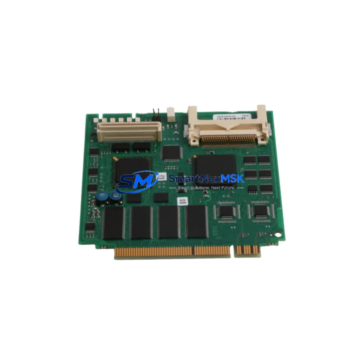
ABB 3BSE050201R1 Maintenance-Ready Spare for AC 800M Automation
The ABB 3BSE050201R1 is an original redundant processor module designed for the AC 800M PM866-2 series distributed control system. In process industries where continuous operation is non-negotiable — oil and gas, power generation, pulp and paper, chemical processing, and water treatment — an unplanned CPU failure can cascade into hours of costly downtime. Stocking a verified 3BSE050201R1 as a maintenance-ready spare is one of the most effective strategies a maintenance or reliability engineer can implement to protect system uptime and reduce mean time to repair (MTTR).
This module serves as the central processing unit in redundant AC 800M controller configurations, executing control logic, managing I/O communication, and maintaining synchronization with its paired redundant CPU. When one processor detects a fault, the standby unit assumes control within milliseconds — but only if the standby hardware is present, healthy, and correctly configured. A missing or degraded spare eliminates that protection entirely.
Every 3BSE050201R1 unit supplied by SMARTNEXMSK undergoes pre-shipment functional verification, is shipped with full ESD protection, and is backed by a 12-month warranty covering manufacturing defects and operational failures under normal industrial conditions.
Spare Maintenance Table
| Parameter | Specification |
|---|---|
| Part Number / SKU | 3BSE050201R1 |
| Manufacturer | ABB (Sweden) |
| Product Series | AC 800M — PM866-2 |
| Module Type | Redundant Processor Module (CPU) |
| Compatible Platform | ABB AC 800M DCS / PLC |
| Redundancy Support | Hot-standby redundant CPU pair |
| Communication Interface | Ethernet (CEX-Bus), ModuleBus |
| Operating Voltage | 24 VDC (via backplane / power supply module) |
| Operating Temperature | 0°C to +55°C |
| Mounting | AC 800M controller backplane (TB820 / TB840 series) |
| Weight | Approx. 1,500 g (with packaging) |
| Country of Origin | Sweden |
| Condition | Original, new or tested-good surplus |
| Warranty | 12 Months — SMARTNEXMSK |
| Pre-Shipment Test | Functional verification performed |
| Shipping | ESD-safe packaging, global express delivery |
Maintenance Planning for Continuous Operation
Replacing or commissioning a 3BSE050201R1 in the field is rarely an isolated task. Experienced maintenance engineers know that a CPU swap is the right moment to inspect the entire controller cabinet for latent faults that could trigger the next unplanned shutdown. The following components should be evaluated as part of any planned or emergency maintenance event involving the PM866-2 processor:
Power Supply Module (SD821 / SD822 / SD823): The AC 800M CPU draws regulated 24 VDC from the controller’s power supply module. A degraded SD821 or SD822 with marginal output voltage can cause intermittent CPU resets that mimic processor faults. Always measure output voltage under load before declaring the CPU as the root cause.
Redundancy Module (RM858): The RM858 redundancy module manages synchronization between the active and standby PM866-2 processors. A faulty RM858 can prevent proper failover even when both CPUs are healthy. Inspect the RM858 for error LEDs and verify synchronization status in the AC 800M engineering tool.
Controller Backplane (TB820 / TB840): The backplane provides the ModuleBus communication path between the CPU and I/O modules. Inspect backplane connectors for corrosion, bent pins, or mechanical damage. A cracked backplane is a common cause of intermittent I/O communication faults that are incorrectly attributed to the processor.
Communication Interface Module (CI854 / CI857 / CI858): PROFIBUS, FOUNDATION Fieldbus, and HART communication modules installed in the same controller rack should be inspected for firmware currency and physical connector integrity. A failing CI854 PROFIBUS interface can generate diagnostic alarms that overload the CPU’s communication buffer.
I/O Modules (AI810, AO810, DI810, DO810): Analog and digital I/O modules in the same S800 I/O cluster should be checked for channel faults, blown fuses, and terminal block integrity. Faulty I/O modules generate continuous error messages that increase CPU load and can mask the true source of a system alarm.
Optical ModuleBus Extender (TB807 / TB811): In distributed cabinet configurations, the optical ModuleBus extender links remote I/O clusters to the main controller. Inspect fiber connectors for contamination and verify signal strength. A degraded optical link is a frequent cause of intermittent I/O loss in large process plants.
Terminal Blocks and Field Wiring: Loose or corroded terminal connections on marshalling panels introduce resistance that can cause analog signal drift and digital input chatter. Torque-check all terminal blocks in the control loop during any planned CPU maintenance window.
Fuses and Circuit Protection: Verify that all 24 VDC supply fuses for the controller rack and field instruments are within rating and show no signs of thermal stress. A nuisance fuse failure during a CPU swap can complicate troubleshooting significantly.
HMI Communication Link: If the plant uses an ABB Operator Workplace (OWS) or third-party SCADA connected via OPC or Ethernet, verify that the HMI communication path is restored and stable after the CPU replacement. A misconfigured IP address or subnet mask on the replacement CPU is a common commissioning error.
Maintaining a documented spare parts list that includes the 3BSE050201R1, the RM858, at least one SD822 power supply, and a set of critical I/O modules (AI810, DI810) provides a practical minimum inventory for sustaining AC 800M-based control systems through their full operational lifecycle — including legacy system life extension programs where OEM support has been discontinued.
Site Replacement Workflow
Step 1 — Pre-Replacement Verification: Before removing the active CPU, confirm that the redundant standby PM866-2 is synchronized and ready to assume control. Check the READY and SYNC LEDs on both the active and standby modules. If the standby is not synchronized, do not proceed with a hot swap — schedule a maintenance window and investigate the RM858 and backplane first.
Step 2 — Configuration Backup: Export the current AC 800M project from ABB Control Builder M and store a timestamped backup on a secure engineering workstation. Confirm that the firmware version of the replacement 3BSE050201R1 matches the existing system. Firmware mismatches between redundant CPU pairs will prevent synchronization.
Step 3 — Module Replacement: With the standby CPU active and controlling the process, remove the faulty active CPU from its backplane slot. Insert the replacement 3BSE050201R1, ensuring the module is fully seated and the locking lever is engaged. The new module will boot and attempt to synchronize with the active CPU automatically.
Step 4 — Synchronization Confirmation: Monitor the SYNC LED on the replacement module. Full synchronization typically completes within 60–120 seconds depending on application size. Confirm synchronization status in Control Builder M before returning the system to normal redundant operation.
Step 5 — Post-Replacement Testing: Verify all I/O channels, communication links, and HMI displays are operating correctly. Check the system event log for any residual alarms. Document the replacement in the plant maintenance management system (CMMS) with the module serial number, date, and technician name.
This workflow applies equally to planned preventive replacements and emergency corrective maintenance, and is compatible with both new and tested-good surplus 3BSE050201R1 units supplied by SMARTNEXMSK.
Spare Parts Support FAQ
Q1: Is the 3BSE050201R1 supplied by SMARTNEXMSK a new or refurbished module?
SMARTNEXMSK supplies both new original and tested-good surplus 3BSE050201R1 units. All surplus units undergo functional verification prior to shipment. The condition is clearly stated on the order confirmation. Both new and tested-good surplus units carry a 12-month warranty.
Q2: How do I verify compatibility between the replacement 3BSE050201R1 and my existing AC 800M system?
Compatibility is determined by the firmware version installed on the replacement module and the AC 800M project version in Control Builder M. Provide your existing CPU firmware version and project revision to our technical team at sales@smartnexmsk.com before ordering, and we will confirm compatibility or supply a firmware-matched unit.
Q3: What is the lead time and shipping arrangement for the 3BSE050201R1?
In-stock units ship within 24–48 hours of order confirmation via international express courier (DHL, FedEx, or UPS). Emergency same-day dispatch is available for critical plant shutdowns. All shipments include tracking, commercial invoice, and ESD-safe packaging documentation.
Q4: What does the 12-month warranty cover, and what is the return process?
The 12-month warranty covers manufacturing defects and operational failures under normal industrial operating conditions. It does not cover damage caused by incorrect installation, overvoltage, or physical impact. To initiate a warranty claim, contact sales@smartnexmsk.com with the order number, module serial number, and a description of the fault. SMARTNEXMSK will arrange return shipping and provide a replacement or full refund within the warranty period.
© 2026 SMARTNEXMSK. All rights reserved.
Original Source: https://smartnexmsk.com
Contact: sales@smartnexmsk.com | +86 18259474341


