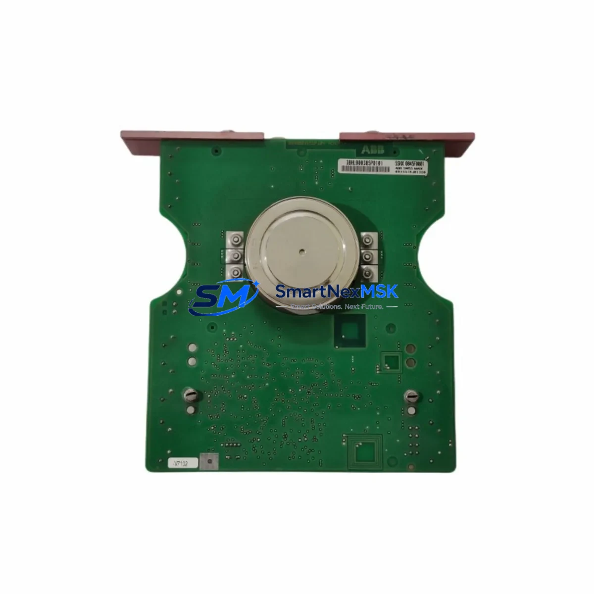
ABB 5SHX0845F0001 Retrofit-Ready Press-Pack IGBT for 5SHX Series Control Systems
The ABB 5SHX0845F0001 (also referenced as 3BHL000385P0101, 5SXE05-0151, and 3BHB003387R0101) is a high-power Press-Pack IGBT module engineered for demanding industrial drive and power conversion applications. As legacy 5SHX and 5SXE series drive systems approach end-of-life or require unplanned replacement, this module serves as the primary retrofit-ready solution for engineers managing aging ABB ACS/ACS6000, MEGADRIVE-LCI, and PCS6000 platforms. With verified compatibility across the 5SHX and 5SXE module families, it enables smooth system modernization without requiring full drive cabinet replacement.
Upgrade Compatibility Table
| Parameter | Details |
|---|---|
| Primary SKU | 5SHX0845F0001 |
| Cross-Reference SKUs | 3BHL000385P0101 / 5SXE05-0151 / 3BHB003387R0101 |
| Compatible Series | ABB 5SHX Series, 5SXE Series |
| Compatible Drive Platforms | ACS6000, MEGADRIVE-LCI, PCS6000, ACS1000 |
| Module Type | Press-Pack IGBT (Integrated Gate Commutated Thyristor compatible stack) |
| Mounting Interface | Press-pack clamp assembly; verify clamping torque per ABB installation guide |
| Cooling Requirement | Liquid-cooled heatsink assembly; confirm coolant flow rate before installation |
| Gate Driver Compatibility | Compatible with ABB AGDR-81C / AGDR-71C gate driver boards |
| Communication Interface | Fiber-optic gate signal; verify fiber connector type on existing driver board |
| Replacement Recommendation | Direct drop-in for 5SXE05-0151; verify DC bus voltage rating before swap |
| Commissioning Focus | Gate threshold voltage, on-state voltage drop, thermal resistance verification |
| Warranty | 12-Month Warranty — covers manufacturing defects and functional failure under normal operating conditions |
Retrofit Planning for Existing Automation Systems
Replacing a Press-Pack IGBT in an operating industrial facility requires systematic pre-work to avoid secondary failures and extended downtime. Before removing the failed 5SHX0845F0001 or its predecessor 5SXE05-0151, engineers should document the existing DC bus voltage, verify the clamping pressure on the press-pack stack, and confirm the coolant inlet temperature and flow rate through the liquid-cooled heatsink assembly.
In ACS6000 and MEGADRIVE-LCI cabinets, the IGBT stack is typically paired with an ABB AGDR-81C or AGDR-71C gate driver board. Before the swap, confirm that the fiber-optic gate signal cables — connecting the gate driver to the IGBT — are undamaged and that the fiber connectors are clean. A contaminated fiber link is a common cause of spurious gate faults after module replacement. If the gate driver board itself shows fault history related to desaturation or overcurrent, consider replacing the AGDR board alongside the IGBT module to eliminate latent failure risk.
For systems running on ABB’s DCS800 or ACS800 control platforms, the replacement process also involves verifying that the drive’s parameter set — particularly current limit, switching frequency, and thermal model coefficients — is backed up using DriveWindow or Drive Composer before any hardware work begins. If the control board (e.g., RDCU-02C or RMIO-11C) has stored adaptive motor model data, this must be preserved to avoid a full motor identification run after restart.
In multi-drive configurations where the 5SHX0845F0001 is part of a parallel IGBT stack — common in high-power LCI (Load Commutated Inverter) topologies — all modules in the same phase leg should be inspected for signs of thermal stress or gate oxide degradation. Replacing a single module in a parallel stack without inspecting its neighbors risks a cascade failure within weeks of restart. The ABB UNITROL 6800 excitation controller and associated I/O modules (e.g., SDCS-IOB-3 or AINT-02C) should also be checked for alarm logs that may indicate upstream causes of the IGBT failure.
For cabinet-level upgrades, the replacement workflow typically involves the following components in sequence: the press-pack IGBT module itself, the gate driver board, the DC bus capacitor bank (if age exceeds 8 years), the snubber capacitor assembly, and the fiber-optic interface cables. In some ACS6000 retrofit projects, the ABB NPBU-12C or NPBU-41C pulse encoder interface board and the RDCO-03C DDCS communication adapter are also replaced to ensure full compatibility with updated firmware on the main control board.
Terminal wiring adaptation is straightforward for direct 5SXE05-0151 replacements, as the press-pack form factor and clamp dimensions are identical. However, engineers should re-torque all bus bar connections to the manufacturer’s specification after installation, as loose connections at high-current terminals are a leading cause of premature IGBT failure in retrofit applications.
Downtime Control During System Migration
Minimizing production downtime during an IGBT replacement in a live industrial facility requires advance preparation and a structured execution plan. The most effective approach is to pre-stage the replacement 5SHX0845F0001 module on-site — verified and tested — before scheduling the maintenance window. This eliminates the risk of discovering a shipping defect or compatibility issue during the outage itself.
Prior to shutdown, capture a full parameter backup from the drive’s control unit using DriveWindow Light or Drive Composer Pro. Export the backup to both a local PC and a USB drive stored in the control cabinet. If the system uses an ABB AC500 PLC or PM591/PM595 controller for sequencing logic, also export the PLC program from Automation Builder to ensure the ladder logic and function block diagrams are preserved independently of the drive backup.
During the replacement window, keep the HMI (e.g., ABB CP600 series or a third-party SCADA panel connected via Modbus TCP or PROFIBUS DP) in manual override mode to maintain visibility of process variables without relying on the drive’s feedback signals. This allows operators to monitor upstream and downstream process conditions — such as motor speed references from a DCS or flow rates from field instruments — while the drive is de-energized.
After installing the new 5SHX0845F0001 and reassembling the press-pack clamp stack, perform a gate drive test at reduced DC bus voltage before applying full load. Verify that the AGDR gate driver board reports no desaturation faults and that the on-state voltage drop across the new module is within the expected range. Restore the parameter backup, confirm communication link integrity on the DDCS or PROFIBUS network, and perform a no-load test run before returning the system to production. A structured commissioning checklist reduces the risk of overlooked steps that could cause a repeat fault within the first hours of operation.
Retrofit Support FAQ
Q1: Is the 5SHX0845F0001 a direct replacement for the 5SXE05-0151?
Yes. The 5SHX0845F0001 is the current production equivalent of the discontinued 5SXE05-0151. Both share the same press-pack form factor, clamping dimensions, and gate signal interface. Verify DC bus voltage rating and gate driver board compatibility (AGDR-81C or AGDR-71C) before installation. No mechanical modification is required for a direct swap.
Q2: What commissioning steps are required after replacing the IGBT module?
After physical installation, perform a gate drive test at reduced bus voltage to confirm the AGDR board is communicating correctly with the new module. Check the fiber-optic gate signal path for continuity and signal integrity. Restore the drive parameter backup, verify thermal model settings, and run a no-load test before applying full motor load. Log all commissioning results for warranty documentation purposes.
Q3: How do I verify wiring and terminal compatibility before the replacement?
The press-pack bus bar connections on the 5SHX0845F0001 are dimensionally identical to the 5SXE05-0151. Re-torque all bus bar bolts to the specified value (refer to ABB installation manual for the ACS6000 or MEGADRIVE-LCI cabinet). Inspect the gate driver fiber connectors for contamination. Confirm coolant hose fittings are compatible with the existing liquid-cooled heatsink assembly before final assembly.
Q4: What does the 12-month warranty cover, and what is required for a warranty claim?
The 12-month warranty covers manufacturing defects and functional failure under normal operating conditions, including gate oxide failure, internal short circuit, and open-circuit faults not caused by external overvoltage or improper installation. To initiate a warranty claim, retain the original shipping documentation, provide a fault description with drive alarm logs, and contact sales@smartnexmsk.com. Modules that show evidence of mechanical damage from improper clamping or coolant contamination are excluded from warranty coverage.
© 2026 SMARTNEXMSK. All rights reserved.
Original Source: https://smartnexmsk.com
Contact: sales@smartnexmsk.com | +86 18259474341


