ABB 5SHY35L4520 Retrofit-Ready IGCT for ACS6000 Control Systems
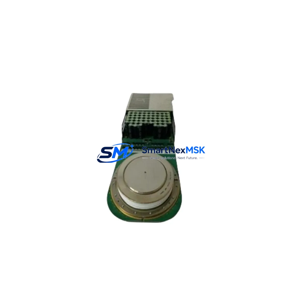
The ABB 5SHY35L4520 is a high-power Integrated Gate-Commutated Thyristor (IGCT) module rated at 4500 V / 3500 A, engineered as a direct retrofit replacement for aging or failed power switching stages in ABB ACS6000 medium-voltage variable-speed drives. Cross-referenced as 5SXE10-0181 and AC10272001R0101, this module is a critical component in drive cabinets where the original IGCT has reached end-of-life, suffered gate-unit failure, or is no longer available through standard OEM channels.
Industrial facilities operating ACS6000 drive systems in compressor trains, pump stations, mill drives, and fan applications frequently encounter the challenge of sourcing discontinued or long-lead-time IGCT modules. The 5SHY35L4520 addresses this directly: it is a form-fit-function equivalent that slots into the existing ACS6000 power stack without requiring structural cabinet modifications, provided the gate unit, snubber circuit, and DC bus connections are verified during commissioning.
Before installation, engineers should confirm the DC bus voltage rating of the existing drive matches the module’s blocking voltage envelope, and that the gate unit type — typically the ABB 5SGX08F0001 or compatible gate driver board — is functional and correctly parameterized. The gate pulse timing, dV/dt snubber values, and thermal interface between the IGCT and the heatsink assembly must all be inspected and re-torqued to OEM specification. Failure to verify these points is the leading cause of premature re-failure in retrofit scenarios.
Each unit shipped by SMARTNEXMSK undergoes a pre-shipment functional check covering gate trigger response, forward voltage drop, and insulation resistance. Units are packaged in anti-static, shock-absorbing enclosures with full traceability documentation. A 12-month warranty is included from the date of delivery.
Upgrade Compatibility Table
| Parameter | Detail |
|---|---|
| Compatible Drive Platform | ABB ACS6000 Medium-Voltage Drive Series |
| Cross-Reference SKUs | 5SHY35L4520 / 5SXE10-0181 / AC10272001R0101 |
| Voltage Rating | 4500 V (blocking voltage) |
| Current Rating | 3500 A (average on-state current) |
| Mounting Interface | Direct stack mount — matches ACS6000 power module bay |
| Gate Unit Compatibility | ABB 5SGX08F0001 gate driver (verify firmware revision) |
| Communication Protocol | Fiber-optic gate pulse link (no fieldbus change required) |
| Cooling Interface | Liquid-cooled heatsink — re-torque and re-seal required |
| Commissioning Requirement | Gate delay calibration, snubber check, DC bus pre-charge test |
| Replacement Recommendation | Replace gate unit simultaneously if drive hours exceed 50,000 h |
| Warranty | 12 months from delivery date |
| Origin | Switzerland (OEM-equivalent specification) |
Retrofit Planning for Existing Automation Systems
A successful ACS6000 retrofit begins well before the replacement module arrives on site. The engineering team should pull the drive’s fault history from the ACS6000 CDP control panel or via the DDCS fiber-optic communication link to the plant DCS — commonly a ABB AC800M controller or ABB Advant OCS platform — to determine whether the IGCT failure was isolated or symptomatic of a wider power-stage degradation.
The power cabinet layout of the ACS6000 typically houses the IGCT stack alongside the ABB 5SDD50N1600 freewheeling diode modules and the ABB BSMB-01 brake chopper module. These components share the same liquid-cooling circuit and DC bus rail, so their condition must be assessed in parallel. If the cooling water manifold shows signs of mineral deposit or flow restriction, it should be flushed before the new IGCT is installed — thermal stress from inadequate cooling is a primary failure driver.
On the control side, the ABB AINT-02 inverter control board and the ABB APBU-44C pulse distribution unit distribute gate firing signals to each IGCT position in the power stack. Verify that all fiber-optic cables between the APBU and the gate units are intact and that the AINT board’s parameter set — particularly the switching frequency, current limit, and fault response thresholds — is backed up before any hardware is disturbed. The ABB DriveWindow software tool is the standard interface for parameter backup and restoration on ACS6000 platforms.
For plants running the ACS6000 in a redundant or bypass configuration, coordinate with the control room to confirm that the bypass contactor logic and the ABB REF615 protection relay interlocks are correctly inhibited during the swap window. This prevents nuisance trips and protects the motor winding from uncontrolled energization during the commissioning phase.
If the retrofit is part of a broader migration from an older ACS6000 to a newer ABB ACS2000 or ABB ACS880 platform, the I/O mapping between the legacy NDIO-01 digital I/O module and the new drive’s I/O terminals must be re-documented. HMI screens built on ABB Panel Builder 800 or third-party SCADA systems will require tag remapping if the drive’s DDCS node address or Modbus register map changes during the upgrade.
Downtime Control During System Migration
Minimizing unplanned downtime during an IGCT replacement on an ACS6000 drive requires a structured pre-outage preparation protocol. The following approach has been validated across multiple industrial retrofit projects:
Pre-outage (48–72 hours before): Complete parameter backup via DriveWindow. Photograph all terminal wiring, fiber-optic routing, and torque-sensitive bus bar connections. Confirm the replacement 5SHY35L4520 module has passed pre-shipment testing and is on-site. Prepare the gate unit calibration procedure and have the snubber resistance values from the original drive documentation available.
During outage: De-energize the drive following the ACS6000 lockout/tagout procedure, including DC bus discharge verification (minimum 15-minute wait after main contactor open, confirmed with a calibrated high-voltage probe). Remove the failed IGCT module, inspect the heatsink surface, apply fresh thermal compound if required, and install the 5SHY35L4520. Reconnect gate unit fiber links and DC bus bars to specified torque values. Perform insulation resistance test on the power circuit before re-energization.
Commissioning: Restore parameters from backup. Run the drive in local control mode at reduced speed (10–15% of rated) to verify gate firing symmetry and current balance across phases. Confirm that the CDP panel shows no active faults and that the DDCS link to the plant DCS has re-established. Gradually ramp to full load under supervision before returning to automatic control.
This structured approach consistently achieves total outage windows of 4–8 hours for a single IGCT replacement, compared to multi-day delays when preparation is inadequate. SMARTNEXMSK can provide pre-shipment test reports and wiring reference documentation to support your site team’s preparation.
Retrofit Support FAQ
Q1: Is the 5SHY35L4520 a direct drop-in replacement for all ACS6000 drive variants?
The 5SHY35L4520 is compatible with ACS6000 drive variants that use the 4500 V / 3500 A IGCT power stack. However, ACS6000 drives are configured in multiple voltage and current ratings. Always confirm your drive’s nameplate data and the original IGCT part number before ordering. Cross-reference 5SXE10-0181 and AC10272001R0101 are accepted equivalents for the same module position.
Q2: Does the replacement module require re-parameterization of the drive?
In most cases, no parameter changes are required if the replacement module is an identical specification match. However, gate delay calibration should be performed after installation to account for unit-to-unit variation in gate trigger response time. This is a standard commissioning step documented in the ACS6000 hardware manual and takes approximately 30–60 minutes with DriveWindow connected.
Q3: What wiring and interface checks are mandatory before powering up?
Prior to re-energization, verify: (1) DC bus bar torque values per OEM specification; (2) fiber-optic gate pulse cables are fully seated and undamaged; (3) cooling water flow is confirmed and no air pockets remain in the circuit; (4) insulation resistance between DC bus and chassis is within acceptable limits; (5) the gate unit is powered and showing a healthy status LED before the main contactor is closed.
Q4: What does the 12-month warranty cover, and how is a claim processed?
The 12-month warranty covers manufacturing defects and premature failure under normal operating conditions consistent with the module’s rated specifications. It does not cover damage resulting from incorrect installation, overvoltage events, or cooling system failure. To initiate a warranty claim, contact SMARTNEXMSK with the shipment documentation, a description of the failure mode, and any available fault log data from the drive. Replacement or repair will be coordinated within 5 business days of claim receipt.
© 2026 SMARTNEXMSK. All rights reserved.
Original Source: https://smartnexmsk.com
Contact: sales@smartnexmsk.com | +86 18259474341


