ABB 70BK06a-E HESG332194 R1 Spare for AC500 Automation: Spare Replacement & Industrial Downtime Risk Control
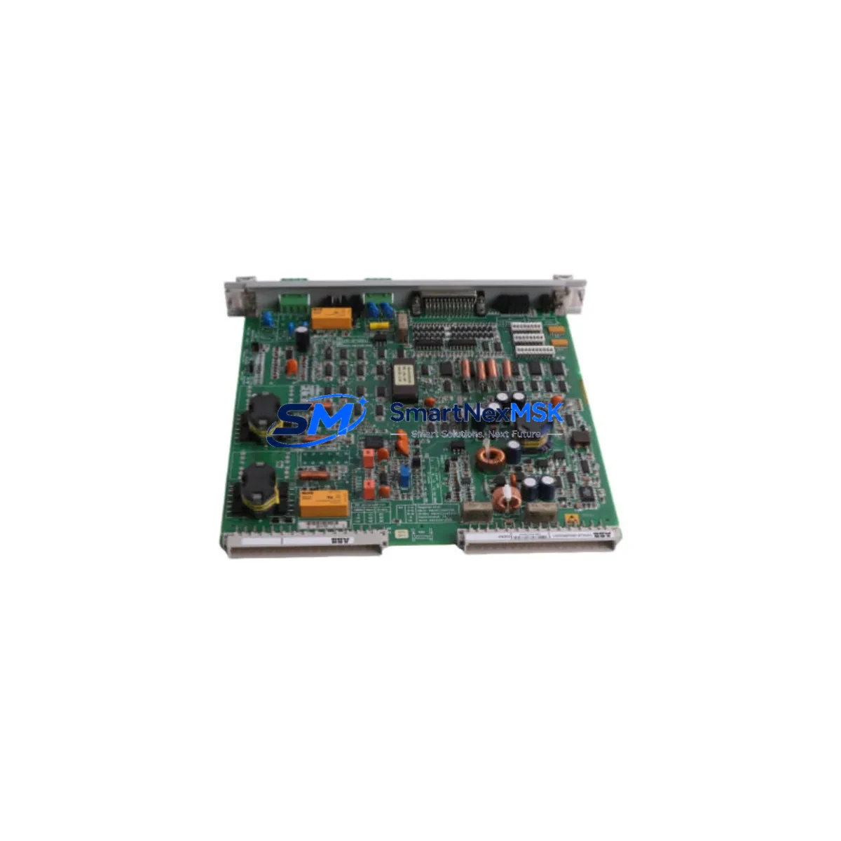
The ABB 70BK06a-E (catalog reference HESG332194 R1) is an original Bus Coupling Module engineered for the ABB AC500 programmable logic controller platform — one of the most widely deployed modular PLC architectures in process automation, machine control, and critical infrastructure applications worldwide. This module forms the communication backbone between the AC500 CPU and its downstream I/O expansion modules. When it fails or degrades, fieldbus communication is interrupted, causing partial or total loss of control loop visibility and triggering unplanned production downtime.
This listing supplies the 70BK06a-E HESG332194 R1 as a maintenance-ready spare: factory-original hardware, pre-shipment functional verification, and backed by a 12-month warranty. Units are dispatched from bonded stock with full traceability documentation, supporting both planned maintenance schedules and emergency breakdown recovery. Whether you are a maintenance engineer executing a scheduled control cabinet inspection or a procurement engineer building a strategic spare parts inventory, this unit ships tested and ready to install.
Spare Maintenance Table
| Parameter | Specification / Detail |
|---|---|
| Part Number | 70BK06a-E |
| Catalog / Order Code | HESG332194 R1 |
| Brand | ABB |
| Series | AC500 PLC Platform |
| Module Function | Bus Coupling Module — fieldbus interface between AC500 CPU and I/O expansion modules |
| Compatible CPU Families | AC500 PM5xx / PM5xx-ETH series (verify rack generation before ordering) |
| Backplane Bus Interface | AC500 internal S-Bus / expansion bus |
| Mounting | DIN rail, AC500 modular rack |
| Operating Voltage | 24 V DC (supplied via backplane) |
| Operating Temperature | -25 °C to +60 °C |
| Protection Class | IP20 |
| Country of Origin | Germany (DE) |
| Unit Weight | 360 g |
| Condition | Original, unused / refurbished-to-spec (state on inquiry) |
| Pre-shipment Test | Functional verification performed before dispatch |
| Warranty | 12 Months |
| Lead Time | In-stock units ship within 1–3 business days |
| Documentation | Datasheet, test report available on request |
Maintenance Planning for Continuous Operation
A Bus Coupling Module failure rarely occurs in isolation. When the 70BK06a-E HESG332194 R1 is flagged for replacement during a scheduled inspection or emergency callout, experienced maintenance engineers treat the event as a trigger for a broader control cabinet audit. The following components share the same electrical environment and should be inspected or held as concurrent spares to prevent repeat failures and reduce future MTTR.
The AC500 CPU module (PM5xx series) drives all bus timing and should be checked for firmware currency and diagnostic fault logs before the new coupling module is commissioned — a corrupted CPU configuration can cause a replacement BK module to appear faulty on first power-up. Alongside the CPU, the 24 V DC power supply module (PS501 or equivalent rack PSU) feeding the backplane should be load-tested under full I/O configuration; an under-voltage condition on the backplane bus is a common root cause of intermittent coupling module errors that are frequently misdiagnosed as module failure.
The AC500 digital I/O expansion modules connected downstream of the bus coupler — including DI524 and DI572 digital input modules, DO524 and DO572 digital output modules — should be visually inspected for connector wear, terminal oxidation, and LED fault indicators. Analog I/O modules such as the AI523 and AO523 should be verified for signal drift, particularly on 4–20 mA process loops where a bus interruption may have caused output freeze or last-value hold conditions that persist after the coupler is restored.
The fieldbus communication module installed in the rack — whether PROFIBUS DP, PROFINET, or Modbus TCP variant — should be verified for correct station address settings and cable termination resistance after any bus coupler swap. Loose or corroded fieldbus cables and D-sub / RJ45 connectors are a frequent secondary fault that re-emerges once the primary module is replaced. Inspect all terminal blocks and wiring ferrules on I/O circuits for tightness, as vibration in industrial environments progressively loosens connections over operational cycles.
For sites running older AC500 racks, it is prudent to hold a spare AC500 backplane rack assembly alongside the bus coupler, as backplane bus contacts degrade with repeated module insertions over years of service. Additionally, 24 V DC miniature circuit breakers and blade fuses protecting the control cabinet power rail should be tested for correct trip characteristics — a nuisance trip during a fault event can mask the true failure mode. Where signal isolators or galvanic isolation barriers are used between field instruments and AC500 analog inputs, inspect these components for thermal damage or calibration drift concurrent with any bus-level fault investigation, as they are often overlooked during reactive maintenance.
Site Replacement Workflow
Step 1 — Compatibility Confirmation: Verify the installed rack generation (AC500 V1 vs V2/V3) and CPU firmware version against the 70BK06a-E HESG332194 R1 datasheet. The R1 revision suffix is critical — confirm it matches your system’s hardware generation to avoid bus protocol mismatches that can prevent module recognition.
Step 2 — Safe Isolation: Place the AC500 CPU in STOP mode via Automation Builder or PS501 Control Builder. De-energize the 24 V DC supply to the rack. Do not hot-swap bus coupling modules unless the CPU documentation explicitly permits it for your installed firmware version.
Step 3 — Module Extraction: Release the DIN rail locking tab, disconnect any external fieldbus connectors, and slide the 70BK06a-E free from the backplane. Note the slot position — the replacement must occupy the identical slot to preserve the I/O address map and avoid configuration errors on restart.
Step 4 — Replacement Installation: Seat the new 70BK06a-E HESG332194 R1 firmly into the backplane slot until the locking tab engages. Reconnect fieldbus cables with correct termination. Restore 24 V DC power. The CPU should automatically detect the new module and resume normal bus scanning within seconds.
Step 5 — Functional Verification: Bring the CPU back to RUN mode. Confirm all downstream I/O modules report healthy status in the diagnostic view. Perform a short I/O loop test on critical channels before returning the system to automatic control. Clear any latched fault codes in the CPU diagnostic buffer.
Step 6 — Documentation: Record the replacement in the site maintenance log with the new module’s serial number, installation date, and test results. This supports warranty claims, future lifecycle planning, and regulatory compliance for sites operating under IEC 62443 or equivalent industrial cybersecurity and maintenance standards.
This workflow minimizes mean time to repair (MTTR) and ensures the replaced module does not introduce new faults into the control system. For legacy AC500 installations approaching end-of-support, maintaining a minimum of one 70BK06a-E HESG332194 R1 in the site spare parts cabinet is strongly recommended to avoid extended lead times during emergency breakdowns.
Spare Parts Support FAQ
Q1: Is the 70BK06a-E HESG332194 R1 compatible with all AC500 CPU variants?
The 70BK06a-E is designed for the ABB AC500 modular PLC platform. Compatibility depends on the specific CPU generation (PM5xx series) and rack hardware revision. We recommend confirming your CPU model and firmware version before ordering. Our technical team can assist with compatibility verification upon request at no charge.
Q2: What pre-shipment testing is performed on each unit?
Every 70BK06a-E HESG332194 R1 unit undergoes functional verification prior to dispatch, including bus communication integrity checks and visual inspection for physical damage. A test report is available on request. Units are packed in anti-static ESD-safe packaging with foam cushioning to prevent transit damage.
Q3: What does the 12-month warranty cover?
The 12-month warranty covers manufacturing defects and functional failures under normal operating conditions consistent with ABB AC500 installation guidelines. It does not cover damage caused by incorrect installation, overvoltage events, or environmental conditions outside the module’s rated specifications. Warranty claims are processed promptly via our sales team at sales@smartnexmsk.com.
Q4: How quickly can I receive the module for an emergency breakdown?
In-stock units are dispatched within 1–3 business days. For critical breakdown situations, contact us directly at +86 18259474341 to confirm real-time stock availability and expedited shipping options. We support both standard and express international freight to minimize your system downtime and get your process back online as fast as possible.
© 2026 SMARTNEXMSK. All rights reserved.
Original Source: https://smartnexmsk.com
Contact: sales@smartnexmsk.com | +86 18259474341


