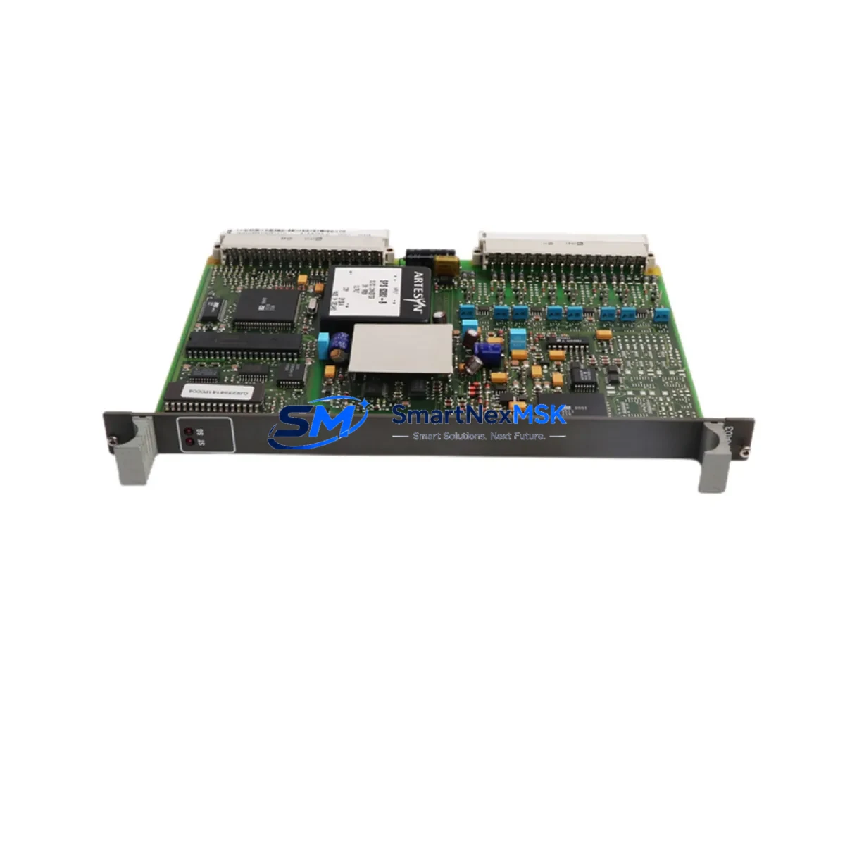
ABB 81AA03A-E GJR2394100R1210 Retrofit-Ready Digital Output Module for AC500 Control Systems
The ABB 81AA03A-E (part number GJR2394100R1210) is a digital output module engineered for the ABB AC500 PLC platform — one of the most widely deployed modular control systems in industrial automation. As legacy AC500 configurations age and original spare parts become increasingly difficult to source, the 81AA03A-E has become a critical retrofit component for engineers managing control cabinet upgrades, production line modernization, and system continuity programs. This module provides reliable DO channel expansion within the AC500 rack architecture, maintaining full compatibility with the existing backplane bus, terminal wiring layouts, and Automation Builder programming environment.
Whether you are replacing a failed output module on an active production line, upgrading an end-of-life control system, or expanding I/O capacity in an existing AC500 cabinet, the 81AA03A-E delivers the electrical and logical compatibility required for a smooth, low-risk transition. Each unit shipped by SMARTNEXMSK is subject to pre-shipment functional verification and is covered by a 12-month warranty from the date of delivery.
Upgrade Compatibility Table
| Parameter | Details |
|---|---|
| Part Number | 81AA03A-E / GJR2394100R1210 |
| Brand / Series | ABB / AC500 |
| Module Type | Digital Output (DO) |
| Backplane Interface | AC500 S500 I/O bus — direct slot insertion |
| Terminal Wiring | Compatible with standard AC500 terminal block layouts; verify conductor cross-section before re-termination |
| Communication Compatibility | Profibus DP, Modbus RTU, CANopen (via AC500 CPU coupler) |
| Replacement Recommendation | Direct replacement for same-series DO modules; confirm channel count and output type (relay/transistor) before installation |
| Commissioning Notes | Module address auto-assigned by rack slot position; verify in Automation Builder I/O configuration after insertion |
| Warranty | 12 months from delivery date — covers manufacturing defects and functional failure under normal operating conditions |
Retrofit Planning for Existing Automation Systems
Successful retrofit of the ABB 81AA03A-E into an existing AC500 control system requires a structured pre-installation review. Engineers should begin by auditing the current rack configuration, confirming available slot positions on the AC500 S500 expansion rack or the CPU-integrated I/O bus. The module slots directly into the backplane without additional adapters, but the surrounding modules — including the PM573, PM583, or PM595 CPU modules — must be verified for firmware compatibility with the current Automation Builder project version.
Power budget is a critical checkpoint. The AC500 power supply module (PS501 or PS502 series) must have sufficient headroom to support the additional DO channel load. Calculate the total current draw across all installed I/O modules, including any TB511, TB521, or TB541 terminal base units, before committing to the retrofit plan. Undersized power supplies are a common cause of intermittent faults after module replacement.
Terminal wiring adaptation is typically straightforward when replacing a like-for-like DO module, but engineers should photograph and document the existing wiring before disconnection. The AC500 uses a removable terminal block design on most I/O modules, which simplifies re-termination and reduces the risk of wiring errors during hot-swap procedures where the control system architecture permits.
For systems using Profibus DP as the primary fieldbus, the CM572-DP communication module must remain active and correctly addressed throughout the retrofit. If the upgrade involves migrating from an older AC31 or AC100 platform to the AC500 architecture, the communication protocol migration plan should include a full mapping of existing Profibus node addresses and a verification pass using the Profibus diagnostic tools available in Automation Builder.
I/O expansion scenarios often involve adding the 81AA03A-E alongside complementary modules such as the DC532 digital input module or the AO523 analog output module to complete a mixed I/O upgrade. In multi-rack configurations, the TB711 or TB721 expansion interface modules are used to extend the I/O bus between racks, and their addressing must be reconfigured in the project after any slot changes.
HMI integration should be validated after module replacement. If the plant uses a CP600 or CP620 operator panel connected to the AC500 CPU via Ethernet or serial link, verify that the HMI screen tags referencing the affected DO channels are correctly mapped to the new module’s I/O addresses. Tag mismatches are a frequent source of post-retrofit alarms that extend commissioning time unnecessarily.
Downtime Control During System Migration
Minimizing unplanned downtime is the primary operational constraint in any live-system retrofit. For the ABB 81AA03A-E replacement, the recommended approach is to prepare a fully tested spare module offline before scheduling the physical swap. Use Automation Builder’s offline simulation mode to verify the updated I/O configuration, confirm that the module address assignment matches the target rack slot, and export a backup of the current project with a clearly labeled version tag before any hardware changes are made.
Where the process allows a controlled shutdown window, coordinate with production scheduling to align the swap with a planned maintenance interval. The physical module exchange on an AC500 rack typically takes under 15 minutes for an experienced technician, but allow additional time for post-installation verification: confirm output channel status via the Automation Builder online monitor, check the diagnostic LED indicators on the 81AA03A-E for normal operating state, and run a functional output test against the connected field devices before returning the system to automatic mode.
For systems where continuous operation is critical, consider a parallel commissioning approach: install and configure the new module in an adjacent rack slot in offline mode, validate all channel assignments and program logic, then perform a rapid cutover during the shortest available process pause. This approach preserves the original program logic and HMI configuration while eliminating the risk of extended downtime caused by unexpected commissioning issues.
Always retain the original project backup and the replaced module (clearly tagged with removal date and fault description) for a minimum of 30 days post-retrofit. This provides a recovery path if post-installation issues are traced to configuration rather than hardware.
Retrofit Support FAQ
Q: Is the ABB 81AA03A-E GJR2394100R1210 a direct drop-in replacement for other AC500 digital output modules?
A: The 81AA03A-E is designed for the AC500 S500 I/O platform and is slot-compatible with the AC500 backplane. However, engineers must verify channel count, output type (transistor vs. relay), and rated output current before substitution. Confirm the replacement module’s specification sheet against the original before installation.
Q: What commissioning steps are required after installing the 81AA03A-E in an existing AC500 rack?
A: After physical installation, open the Automation Builder project and verify the I/O configuration reflects the correct module type in the target slot. Download the updated configuration to the CPU (PM573/PM583/PM595), confirm the module’s diagnostic LEDs show normal status, and perform a channel-by-channel output test using the force function in online mode before releasing the system to production.
Q: Can the 81AA03A-E be used in systems communicating via Modbus RTU or CANopen in addition to Profibus DP?
A: Yes. The 81AA03A-E is an I/O module that communicates via the AC500 internal I/O bus. The fieldbus protocol (Profibus DP, Modbus RTU, CANopen, or Ethernet/IP) is managed by the CPU and communication modules (CM572-DP, CM575-DN, etc.) independently of the I/O module type. The 81AA03A-E is compatible with any AC500 CPU regardless of the external fieldbus in use.
Q: What does the 12-month warranty cover, and what is the process for a warranty claim?
A: The 12-month warranty covers manufacturing defects and functional failure under normal operating and storage conditions from the date of delivery. To initiate a warranty claim, contact SMARTNEXMSK with the order reference, a description of the fault, and photographic evidence of the module condition. Replacement or repair will be arranged within the warranty period at no additional cost to the buyer.
© 2026 SMARTNEXMSK. All rights reserved.
Original Source: https://smartnexmsk.com
Contact: sales@smartnexmsk.com | +86 18259474341


