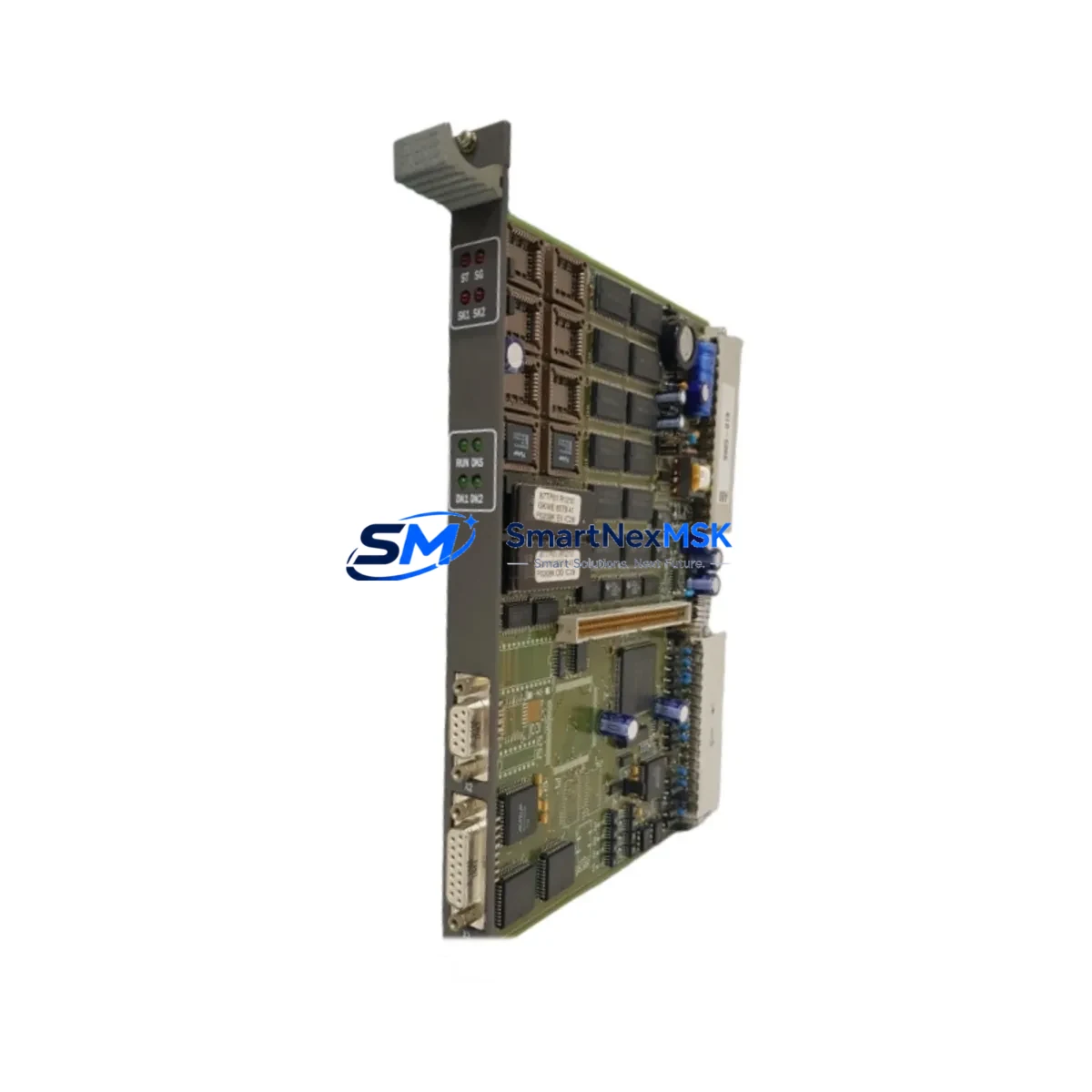
ABB 87TP01 Retrofit-Ready PROFIBUS DP Coupler for AC500 S500 Control Systems
The ABB 87TP01 is a PROFIBUS DP coupler module engineered for seamless integration within the ABB AC500 and S500 distributed I/O architecture. As legacy control systems age and original components reach end-of-life, the 87TP01 serves as a verified retrofit solution for engineers managing brownfield upgrades, panel refurbishments, and communication protocol migrations. Whether you are replacing a failed coupler on an active production line or planning a phased modernization of an aging control cabinet, the 87TP01 delivers the electrical and protocol compatibility required to maintain system continuity without forcing a full platform replacement.
In retrofit scenarios, the 87TP01 connects S500 I/O expansion modules — including digital input modules such as the DI524, digital output modules such as the DO524, and analog modules such as the AI523 and AO523 — to the PROFIBUS DP network managed by an AC500 CPU, typically a PM554, PM564, or PM583 series controller. The coupler acts as the bus interface between the field-level I/O bus and the PROFIBUS DP segment, allowing engineers to retain existing field wiring and terminal assignments while upgrading the communication backbone or replacing a defective coupler unit.
Before installation, retrofit engineers should verify the power supply capacity of the existing control cabinet. The S500 I/O bus requires a dedicated 24 VDC supply, and the TB521 or TB541 power supply terminal units must be confirmed as functional and correctly rated for the expanded I/O load. Terminal wiring on the existing I/O modules should be documented and photographed prior to any module removal to preserve field wiring integrity during the swap.
Backplane and rack compatibility is a critical checkpoint. The 87TP01 is designed for direct insertion into the S500 I/O bus rail. Engineers should confirm that the existing bus rail and end cap assembly are undamaged and that the module address settings — configured via rotary switches on the coupler — match the PROFIBUS node address previously assigned in the AC500 CPU program. Mismatched node addresses will prevent the CPU from recognizing the coupler on the PROFIBUS segment and will generate diagnostic faults in the engineering tool, typically Automation Builder.
Program compatibility should be assessed before the replacement module is powered. If the original 87TP01 was configured with a specific GSD file version in the PROFIBUS master configuration, the replacement unit must use the same GSD file to ensure that the I/O mapping, diagnostic byte structure, and cyclic data exchange parameters remain consistent. Any deviation may require a partial recompile and download of the CPU program, which should be planned during a scheduled maintenance window to avoid unplanned downtime.
HMI screens connected to the AC500 CPU via Modbus TCP or CS31 — often running on CP600 or CP635 panel PCs — should be reviewed to confirm that any diagnostic or status displays referencing the PROFIBUS coupler node remain valid after the replacement. In most cases, HMI logic referencing I/O addresses rather than hardware diagnostics will continue to function without modification.
Communication link integrity should be verified after installation using the PROFIBUS diagnostic tools available in Automation Builder or a standalone PROFIBUS analyzer. Bus termination resistors at both ends of the PROFIBUS segment must be confirmed as active, and cable shielding continuity should be checked, particularly in environments with high electromagnetic interference from variable frequency drives or large motor starters sharing the same control cabinet.
Field commissioning of the 87TP01 replacement typically involves a cold-start sequence: power down the I/O bus, seat the new coupler, restore power, and observe the LED status indicators on the module face. A steady green RUN LED confirms successful PROFIBUS communication establishment. A flashing or red BF (Bus Fault) LED indicates a configuration mismatch or physical layer issue that requires further investigation before returning the system to automatic operation.
Upgrade Compatibility Table
| Parameter | Details |
|---|---|
| Compatible Platform | ABB AC500 / S500 Distributed I/O |
| Communication Protocol | PROFIBUS DP (EN 50170) |
| Bus Interface | S500 I/O Bus Rail (direct insertion) |
| Node Address Configuration | Rotary switch, 1–125 |
| Supply Voltage | 24 VDC via S500 bus power terminal |
| Compatible CPUs | PM554, PM564, PM572, PM583, PM591, PM595 |
| Compatible I/O Modules | DI524, DO524, AI523, AO523, DC532, DA501 |
| GSD File Requirement | Must match original master configuration |
| Replacement Scope | Drop-in; no rack modification required |
| Commissioning Tool | ABB Automation Builder |
| Warranty | 12 Months from date of shipment |
Retrofit Planning for Existing Automation Systems
A successful 87TP01 retrofit begins with a complete audit of the existing PROFIBUS segment. Engineers should map all active nodes on the bus, including other S500 coupler stations, remote I/O drops, and any third-party PROFIBUS slaves such as Siemens ET 200S distributed I/O or Danfoss VLT drive units sharing the same network segment. The 87TP01 replacement must not disrupt the bus topology or alter termination states for adjacent nodes.
Power distribution within the control cabinet should be reviewed. If the existing TB521 power supply terminal is operating near its rated output current, adding or replacing a coupler station may require upgrading to a TB541 or installing an additional 24 VDC power supply rail. The TA526 bus terminal adapter and TU515 or TU516 terminal units used with analog I/O modules should also be inspected for corrosion or loose connections that may have contributed to the original coupler failure.
For systems where the AC500 CPU communicates with an upstream SCADA or DCS via Ethernet — using the CM572-DP or CM589-PNIO communication modules — the PROFIBUS retrofit at the field level is transparent to the higher-level network, provided the I/O data structure remains unchanged. This allows the 87TP01 replacement to be completed without modifying OPC server tag configurations or historian data mappings.
Programming cables such as the TK501 USB programming cable should be on hand during commissioning to allow direct CPU connection for online diagnostics and, if necessary, a partial program download to update the hardware configuration after the coupler replacement.
Downtime Control During System Migration
Minimizing production downtime during a PROFIBUS coupler replacement requires advance preparation. Before the maintenance window opens, the replacement 87TP01 should be bench-tested with a known-good AC500 CPU and a representative S500 I/O configuration to confirm module functionality and correct LED behavior. The existing CPU program should be backed up to a CF card or USB memory using the Automation Builder project archive function, preserving all hardware configuration, symbol tables, and POU logic.
During the physical swap, field wiring on the S500 I/O modules connected to the coupler station does not need to be disturbed, as the wiring terminates on the TU515 or TU516 terminal units rather than on the coupler itself. This significantly reduces reconnection risk and shortens the maintenance window. After seating the replacement coupler and restoring bus power, the CPU should be placed in STOP mode before switching to RUN to allow the PROFIBUS master to complete its initialization scan and confirm all configured slave nodes are online before resuming automatic control.
If the system controls a continuous process where even a brief interruption is unacceptable, consider pre-configuring a hot-standby arrangement using a redundant AC500 CPU pair with the PM573 or PM591 redundancy module, allowing the PROFIBUS coupler replacement to be performed on the standby branch without affecting the active control path.
Retrofit Support FAQ
Q: Is the ABB 87TP01 a direct drop-in replacement for a failed coupler on an existing S500 I/O station?
A: Yes. The 87TP01 installs directly onto the S500 bus rail without rack modification. Set the rotary node address switches to match the original coupler’s PROFIBUS address before powering the station.
Q: Do I need to modify my AC500 CPU program after replacing the 87TP01?
A: In most cases, no. If the replacement coupler uses the same GSD file version and the node address is correctly set, the CPU will recognize the new module transparently. A program download is only required if the hardware configuration in Automation Builder needs to be updated due to a GSD version change.
Q: What pre-shipment testing is performed on the 87TP01?
A: Each unit undergoes functional verification including PROFIBUS communication establishment, I/O bus power integrity, and LED status confirmation before shipment. Units are supplied with a 12-month warranty covering manufacturing defects and functional failures under normal operating conditions.
Q: Can the 87TP01 be used in a mixed PROFIBUS segment with non-ABB slaves?
A: Yes. The 87TP01 complies with the EN 50170 PROFIBUS DP standard and can coexist on a segment with third-party PROFIBUS DP slaves, provided bus termination, cable length, and baud rate settings are correctly configured for the entire segment.
© 2026 SMARTNEXMSK. All rights reserved.
Original Source: https://smartnexmsk.com
Contact: sales@smartnexmsk.com | +86 18259474341


