ABB 88FN02B-E GJR2370800R0200 Retrofit-Ready Coupling Module for Advant AC31 Control Systems
The ABB 88FN02B-E (part number GJR2370800R0200) is a coupling module designed for the Advant AC31 programmable controller series — one of ABB’s most widely deployed distributed control platforms in process automation, power distribution, and discrete manufacturing. As the AC31 series approaches end-of-life and spare parts become increasingly scarce, the 88FN02B-E has become a critical retrofit component for engineers tasked with extending the operational life of existing control cabinets or executing a phased migration to modern platforms such as the ABB AC500 series.
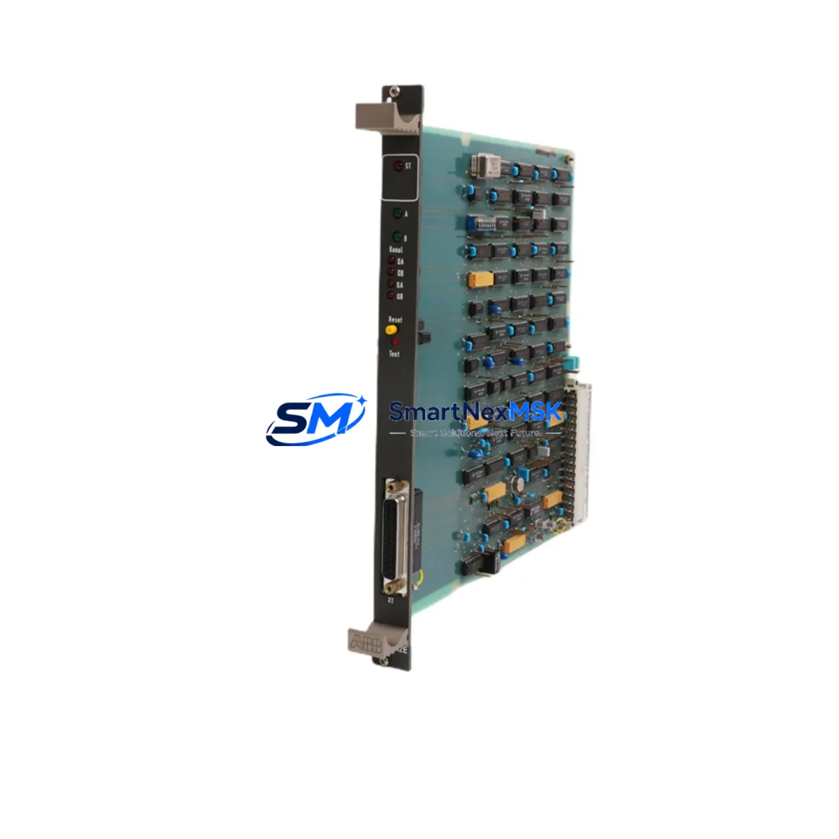
This module serves as a direct replacement for failed or aging coupling units within AC31 rack assemblies. It interfaces with the AC31 backplane bus, enabling communication between the central processing unit and distributed I/O nodes. When sourcing a replacement, engineers must verify the backplane slot assignment, bus termination settings, and module address configuration to ensure seamless re-integration without reprogramming the host CPU — typically an ABB PM564, PM581, or legacy AC31 processor card.
Upgrade Compatibility Table
| Parameter | Details |
|---|---|
| Part Number | 88FN02B-E / GJR2370800R0200 |
| Brand / Series | ABB / Advant AC31 |
| Module Function | Coupling Module — backplane bus interface |
| Mounting | DIN rail / AC31 rack backplane slot |
| Communication Compatibility | AC31 internal bus; compatible with PROFIBUS-DP nodes via gateway modules |
| Replacement Scope | Direct drop-in for same-slot AC31 coupling positions |
| Interface Compatibility | Compatible with AC31 I/O modules: 07AI91, 07AO91, 07DI92, 07DO92 series |
| Power Supply Requirement | Verify 24 VDC rack supply capacity before installation; confirm with PS560 or equivalent ABB power supply module |
| Commissioning Notes | Confirm module address via DIP switch; validate with AC31 programming tool (907 PC331 or ABB Automation Builder) |
| Warranty | 12 Months — covers manufacturing defects and functional failure under normal operating conditions |
Retrofit Planning for Existing Automation Systems
Successful integration of the 88FN02B-E into an existing AC31 control system requires a structured pre-installation audit. Begin by documenting the current rack layout, including the positions of all installed modules such as the 07DI92 digital input module, 07DO92 digital output module, 07AI91 analog input module, and any installed 07AO91 analog output modules. Photograph all terminal wiring before disconnection, and record the DIP switch settings on the outgoing coupling module to replicate the address configuration on the replacement unit.
Power supply capacity is a frequent oversight in retrofit projects. The ABB PS560 or PS501 power supply modules feeding the AC31 rack must be verified to support the full load of all installed I/O and communication modules after the coupling module is replaced. If the rack is operating near its rated current draw, consider redistributing I/O across an additional sub-rack connected via a CS31 bus cable, which the 88FN02B-E supports as part of the AC31 distributed I/O architecture.
For systems that include PROFIBUS-DP communication, confirm that the DP master module — such as the ABB 07KP90 or a compatible PROFIBUS interface card — retains its GSD file configuration and station address assignments after the coupling module swap. In many legacy installations, the coupling module participates in the internal address map that the PROFIBUS master references; any mismatch will cause communication faults on the DP network.
HMI panels connected to the AC31 system — including ABB CP600 series operator panels or third-party SCADA systems communicating via Modbus RTU or CS31 protocol — should be tested in simulation mode before the live cutover. Verify that all process variable tags mapped to I/O channels served by the 88FN02B-E coupling path are reading correctly after module replacement. If the system uses an ABB 07KT98 or 07KT97 CPU, confirm that the hardware configuration stored in the CPU’s flash memory matches the new module arrangement.
Terminal wiring on the AC31 rack uses standard screw-clamp connectors. When reconnecting field wiring after module replacement, use the original wiring diagram and verify continuity on all signal and shield conductors before powering up. Pay particular attention to analog signal shielding — improper grounding of shield conductors on the 07AI91 analog input module can introduce noise that masks the successful operation of the newly installed coupling module.
Downtime Control During System Migration
Minimizing production downtime during an AC31 coupling module replacement requires advance preparation and a disciplined cutover sequence. Before scheduling the maintenance window, obtain a full backup of the AC31 application program using the 907 PC331 programming software or ABB Automation Builder. Store the backup on at least two independent media — a local engineering workstation and a removable drive kept off-site — to protect against data loss during the hardware swap.
Where the process permits, perform a controlled shutdown of the affected control loop rather than an emergency stop. This preserves the last known output states and allows field devices — including actuators, drives, and sensors wired through the AC31 I/O — to reach a safe resting position before power is removed from the rack. If the system includes a redundant CPU configuration, activate the standby CPU before removing the coupling module to maintain control continuity on non-affected I/O channels.
After installing the 88FN02B-E, power up the rack in stages: first verify the 24 VDC bus voltage at the backplane connector, then confirm that the CPU recognizes the new module in its hardware scan. Use the diagnostic LEDs on the coupling module to verify bus communication status before re-enabling field outputs. A typical cold-start commissioning sequence — from power-off to verified I/O operation — takes 30 to 90 minutes for an experienced engineer familiar with the AC31 platform, making the 88FN02B-E one of the more time-efficient retrofit options available for this control generation.
Once the system is back online, run a full I/O check against the process P&ID to confirm that all field signals are reading within expected ranges. Document the completed replacement in the site maintenance log, including the new module’s serial number, installation date, and DIP switch configuration, to support future troubleshooting and warranty claims.
Retrofit Support FAQ
Q: Is the 88FN02B-E a direct replacement for the original GJR2370800R0200 installed in my AC31 rack?
A: Yes. The 88FN02B-E carries the ABB part number GJR2370800R0200 and is a form-fit-function replacement for the same coupling module position in the AC31 rack. No hardware modifications to the backplane or adjacent modules are required, provided the DIP switch address settings are replicated from the outgoing unit.
Q: What commissioning steps are required after installation?
A: After seating the module in the rack, verify the DIP switch address matches the original configuration. Power up the rack and confirm the CPU performs a successful hardware scan — the module’s RUN LED should illuminate steady green. Use 907 PC331 or ABB Automation Builder to perform an online comparison of the hardware configuration. Run a full I/O force test on all channels served by the coupling path before returning the system to automatic mode.
Q: Will my existing field wiring and terminal connections need to be modified?
A: No terminal wiring changes are required for a like-for-like coupling module replacement. The 88FN02B-E uses the same backplane connector and does not have direct field terminal connections — field wiring remains on the I/O modules (07DI92, 07DO92, 07AI91, 07AO91) which are not disturbed during the coupling module swap.
Q: What does the 12-month warranty cover?
A: The 12-month warranty covers manufacturing defects and functional failure under normal operating conditions from the date of shipment. Each unit undergoes pre-shipment functional testing to verify bus communication and power integrity. Warranty claims are supported by our technical team — contact sales@smartnexmsk.com with the module serial number and a description of the fault condition.
© 2026 SMARTNEXMSK. All rights reserved.
Original Source: https://smartnexmsk.com
Contact: sales@smartnexmsk.com | +86 18259474341


