ABB ACS350-03E-05A6-4 Retrofit-Ready VFD for ACS350 Control Systems
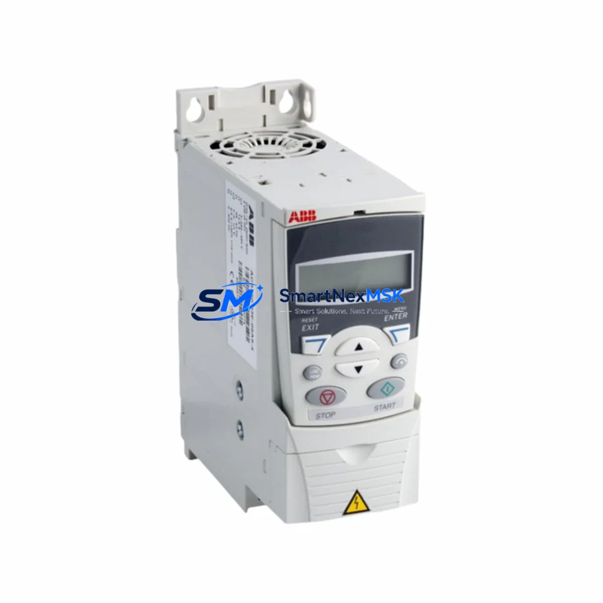
The ABB ACS350-03E-05A6-4 is a 2.2 kW, 400 V three-phase variable frequency drive engineered for seamless integration into existing ACS350-series automation architectures. Whether you are replacing a failed unit on a legacy production line, upgrading an aging control cabinet, or migrating from an earlier ABB drive platform, this module delivers the electrical and mechanical compatibility required to restore full operation with minimal downtime. Its compact footprint, standard R2 frame size, and native support for ABB’s DriveWindow and DriveStudio commissioning environments make it a preferred choice for retrofit engineers and maintenance teams managing aging industrial assets.
Procurement teams sourcing this drive as a direct replacement for discontinued or end-of-life units will find that the ACS350-03E-05A6-4 retains full backward compatibility with the ACS350 parameter set, eliminating the need to rewrite PLC logic or reconfigure SCADA tag mappings. The drive ships pre-tested against ABB factory acceptance criteria and is accompanied by a 12-month warranty covering manufacturing defects and functional failures under normal operating conditions.
Upgrade Compatibility Table
| Parameter | ACS350-03E-05A6-4 (This Unit) | Retrofit Notes |
|---|---|---|
| Power Rating | 2.2 kW (3 HP) | Verify motor nameplate; derate if ambient >40 °C |
| Supply Voltage | 380–480 V AC, 3-phase | Confirm incoming bus voltage before wiring |
| Output Current | 5.6 A continuous | Match to motor FLA; check cable sizing |
| Frame Size | R2 | Direct DIN-rail or panel mount; same footprint as prior R2 units |
| Control Terminals | Standard ACS350 I/O block (X1) | Terminal mapping identical to ACS350-03E series; no rewiring required |
| Fieldbus / Communication | Modbus RTU (built-in); optional PROFIBUS, DeviceNet, EtherNet/IP via FMBA/FDNA/FENA adapter | Retain existing fieldbus adapter if upgrading from same series |
| Parameter Compatibility | Full ACS350 parameter set | Upload backup from DriveWindow before swap; restore after commissioning |
| Braking Chopper | Built-in (external resistor required) | Reuse existing braking resistor if within specification |
| Installation Standard | IEC 61800-5-1, UL 508C | Suitable for CE and UL-marked control panels |
| Warranty | 12 months from date of shipment — covers manufacturing defects and functional failures under rated operating conditions | |
Retrofit Planning for Existing Automation Systems
A successful retrofit of the ACS350-03E-05A6-4 begins well before the drive arrives on site. Engineers should start by auditing the existing control cabinet to confirm available DIN-rail space, incoming power bus capacity, and the condition of the motor cable and grounding conductors. Because the ACS350 platform uses a standardized I/O terminal block layout, the field wiring from the previous drive — including analog speed reference inputs, digital run/stop commands, and relay output connections — can typically be transferred directly without modification.
If the legacy system relied on an ABB ACS355 or an earlier ACS150 as an interim replacement, note that the parameter group structure differs slightly; a full parameter comparison using DriveStudio is recommended before going live. For sites running ABB ACS800 or ACS880 drives in adjacent cabinet sections, the Modbus RTU network topology can be extended to include the new ACS350-03E-05A6-4 without reconfiguring the master PLC — simply assign a unique node address and update the drive register map in the SCADA or DCS configuration.
Power supply integrity is critical during any drive swap. Confirm that the ABB PSR or PST series soft starter or the upstream circuit breaker feeding the drive bay is rated for the inrush current profile of the ACS350 at startup. If the cabinet also houses an ABB ACSM1 motion control module or a FENA-21 EtherNet/IP adapter on an adjacent drive, ensure the 24 V DC auxiliary supply — often sourced from an ABB CP-D 24/1.3 power supply unit — has sufficient headroom after adding the new drive’s control circuit load.
For I/O-intensive applications, engineers frequently pair the ACS350-03E-05A6-4 with an ABB RETA-02 Ethernet adapter or a RPBA-01 PROFIBUS adapter to integrate the drive into a broader distributed control system. If the existing backplane or rack hosts an ABB AC500 PLC with PM573 or PM583 CPU modules, the drive can be addressed directly over Modbus RTU using standard function codes, preserving the original ladder logic without modification. HMI screens built on ABB CP600 or CP400 panels typically require only a tag address update to reflect the new drive node, not a full screen redraw.
Before energizing the replacement drive, verify that the motor thermal model parameters (groups 30 and 35 in the ACS350 parameter set) are correctly restored from the backup file. Incorrect overload settings are a leading cause of nuisance trips during the first hours of post-retrofit operation. All units supplied by SMARTNEXMSK undergo a pre-shipment functional test covering power-on self-test, output voltage symmetry, and communication link verification, reducing the risk of commissioning failures caused by transit damage or latent defects.
Downtime Control During System Migration
Minimizing production downtime during a drive replacement requires a structured migration sequence. The recommended approach is to perform a full parameter backup using ABB DriveWindow Light 2 or DriveStudio while the original drive is still operational — even if it is running in a degraded state. This backup preserves motor data, ramp times, PID tuning, and all application macro settings, allowing the replacement ACS350-03E-05A6-4 to be pre-configured on the bench before the scheduled maintenance window begins.
During the physical swap, label all field wiring before disconnection and photograph the terminal block layout. The ACS350’s X1 control terminal block is removable, which means the entire wiring harness can be unplugged from the old drive and plugged directly into the new unit — eliminating individual wire-by-wire reconnection and reducing the risk of miswiring errors. After mechanical installation, restore the parameter backup, verify motor rotation direction with a short jog command at low frequency (typically 5–10 Hz), and confirm that all digital inputs and analog feedback signals are reading correctly before returning the drive to automatic control.
For processes where even a brief interruption is unacceptable, consider staging the new drive in a parallel test circuit using a load bank or a spare motor before the cutover. This approach allows full functional verification — including fieldbus communication, PLC handshake signals, and HMI status displays — without touching the live production circuit. Once verified, the cutover itself can be completed in under 30 minutes for a standard ACS350 R2 installation, keeping total planned downtime well within a single shift maintenance window.
Retrofit Support FAQ
Q1: Is the ACS350-03E-05A6-4 a direct drop-in replacement for other ACS350-03E variants?
Yes. All ACS350-03E-xxxxx-4 drives share the same control terminal layout, parameter structure, and mounting dimensions within their respective frame sizes. The ACS350-03E-05A6-4 (R2 frame, 5.6 A) can replace any R2-frame ACS350-03E unit provided the motor load does not exceed the output current rating. No changes to field wiring or PLC programming are required.
Q2: Can I reuse the existing fieldbus adapter from the old drive?
In most cases, yes. ABB fieldbus adapters such as the FMBA-01 (Modbus), RPBA-01 (PROFIBUS DP), FDNA-01 (DeviceNet), and FENA-21 (EtherNet/IP) are mechanically and electrically compatible across the ACS350 series. Remove the adapter from the old drive, install it in the option slot of the new unit, and restore the communication parameters from your backup file. Confirm the adapter firmware version is compatible with the replacement drive’s firmware revision before commissioning.
Q3: What commissioning checks are required after installation?
After restoring the parameter backup, perform the following verification sequence: (1) confirm supply voltage is within 380–480 V AC ±10%; (2) run the motor ID run (parameter 99.15) if the motor data has changed; (3) verify all digital input states match expected PLC outputs using the drive’s I/O monitoring display; (4) check analog input scaling for speed reference signals; (5) confirm fieldbus communication status and node address; (6) perform a low-speed jog to verify rotation direction and encoder feedback if applicable. Document all readings before returning the drive to automatic mode.
Q4: What does the 12-month warranty cover, and how is a claim initiated?
The 12-month warranty covers manufacturing defects, component failures, and functional non-conformance under rated operating conditions from the date of shipment. It does not cover damage caused by incorrect installation, overvoltage events, water ingress, or operation outside the specified ambient temperature range. To initiate a warranty claim, contact SMARTNEXMSK with the order reference number, a description of the fault symptom, and any available fault code history from the drive’s event log. Replacement or repair will be arranged within the warranty period at no additional cost.
© 2026 SMARTNEXMSK. All rights reserved.
Original Source: https://smartnexmsk.com
Contact: sales@smartnexmsk.com | +86 18259474341


