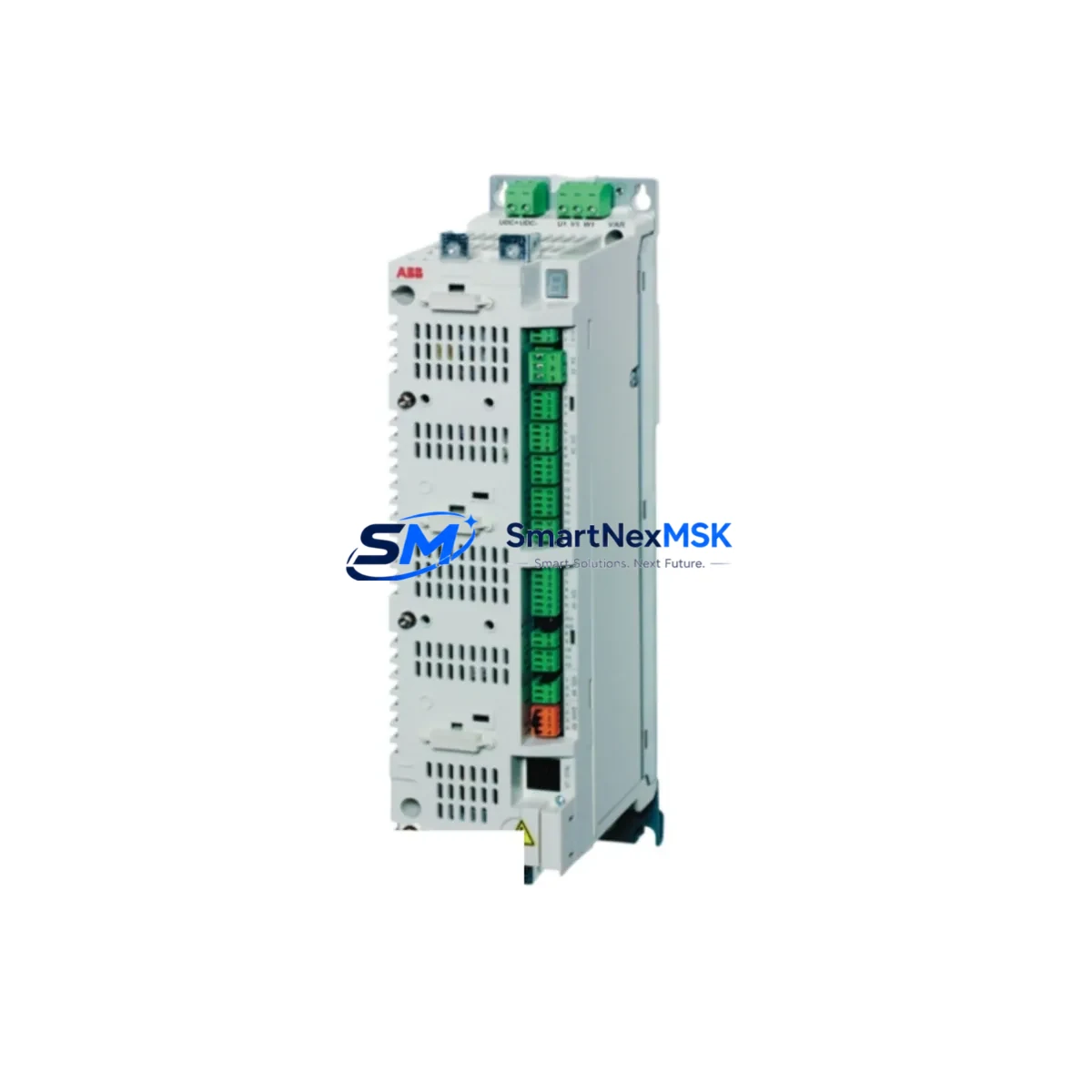
ABB ACSM1-04AM-09A5-4+L517 Retrofit-Ready AC Drive for ACSM1 Control Systems
The ABB ACSM1-04AM-09A5-4+L517 is a 4 kW, 400 V three-phase AC drive from ABB’s ACSM1 series, engineered for high-performance motion control in demanding industrial environments. As legacy ACSM1 installations age and original spare parts become increasingly scarce, this unit serves as a verified retrofit-ready replacement that preserves existing control architecture while delivering modern drive performance. Whether you are managing a planned upgrade cycle or responding to an unplanned drive failure, the ACSM1-04AM-09A5-4+L517 provides a reliable, specification-matched solution with minimal disruption to your production line.
The ACSM1 series was widely deployed across servo-class motion applications including CNC axes, winding machines, printing lines, and multi-axis coordinated systems. The +L517 option code indicates the inclusion of the Safe Torque Off (STO) safety function, which is essential for machinery directive compliance in European and export markets. When replacing a failed or end-of-life unit, confirming that the replacement carries the same option codes — including L517 — is a critical step that is often overlooked during emergency procurement.
Upgrade Compatibility Table
| Parameter | Detail |
|---|---|
| SKU / Model | ACSM1-04AM-09A5-4+L517 |
| Brand | ABB |
| Series | ACSM1 (Motion Control Drive) |
| Power Rating | 4 kW |
| Voltage | 380–480 V AC, 3-phase |
| Output Current | 9.5 A continuous |
| Option Code +L517 | Safe Torque Off (STO) — EN 61800-5-2 compliant |
| Mounting | DIN rail / panel mount, standard ACSM1 footprint |
| Communication | Compatible with DDCS, CANopen, PROFIBUS-DP, EtherCAT via fieldbus adapter |
| Encoder Interface | TTL / HTL / Resolver via ACSM1-ENC option module |
| Replacement Fit | Direct drop-in for ACSM1-04AM-09A5-4 variants with L517 option |
| Commissioning Tool | DriveStudio / Drive Composer (PC USB cable OPCA-01 or FCAN-01) |
| Warranty | 12 months from date of shipment |
| Pre-shipment Test | Power-on functional test performed before dispatch |
Retrofit Planning for Existing Automation Systems
Successful retrofit of the ACSM1-04AM-09A5-4+L517 into an existing control cabinet begins with a thorough audit of the surrounding system. In most ACSM1 installations, the drive shares a backplane or control cabinet with companion components including the ACSM1-04AS-04A0-4 (a lower-current servo variant on the same axis group), ACSM1 DDCS fiber optic link modules for master-follower axis synchronization, and ABB ACS880 or ACS580 drives on auxiliary axes that share the same DC bus or common DC link architecture.
Before removing the failed unit, document the terminal wiring on the control board connector X1 (digital I/O), X2 (analog I/O), and X4 (STO circuit). The STO wiring connected to the +L517 option must be verified against the safety relay output — typically an ABB PNOZ or Pilz safety relay — to ensure the STO channel is correctly re-terminated on the replacement unit. Incorrect STO wiring will prevent the drive from enabling and may trigger a fault on the safety PLC, which in many installations is a ABB AC500 Safety PLC or a Siemens S7-300F / S7-1500F safety controller.
For systems using fieldbus communication, confirm the node address and baud rate settings stored in the original drive’s parameters before replacement. ACSM1 drives using FPBA-01 PROFIBUS-DP adapter or FECA-01 EtherCAT adapter must have their node address re-configured on the new unit to match the master PLC’s device table. In Siemens TIA Portal or Step 7 environments, the GSD/GSDML file must match the firmware version of the replacement drive. Similarly, in Rockwell Studio 5000 environments using EtherNet/IP via FENA-21 adapter, the EDS file and IP address assignment must be re-applied.
Encoder feedback wiring is another critical checkpoint. If the original axis used a resolver or TTL incremental encoder connected through the ACSM1-ENC encoder interface module, verify that the encoder cable shield grounding and differential signal integrity are maintained after reconnection. A mismatched encoder resolution parameter (pulses per revolution) will cause speed loop instability or position error faults immediately upon first enable.
Power supply capacity must also be confirmed. The ACSM1-04AM-09A5-4+L517 draws from the main AC supply through an upstream ABB ACS880 common DC bus supply unit or directly from a three-phase supply via an input choke. Verify that the upstream circuit breaker, input fuse, and EMC filter (such as the ABB NOCH0010-62 or equivalent) are rated for the drive’s input current. In multi-drive cabinets, the total connected load must not exceed the supply transformer’s rated capacity.
Downtime Control During System Migration
Minimizing production downtime during an ACSM1 drive replacement requires preparation before the maintenance window begins. The most effective approach is to use DriveStudio or Drive Composer Pro to perform a full parameter backup of the original drive via the USB service port (OPCA-01 cable) while the machine is still operational. This backup file captures all motor data, speed/torque loop tuning, I/O configuration, fieldbus settings, and application macro parameters. Upon installation of the ACSM1-04AM-09A5-4+L517, the parameter set can be restored in minutes, eliminating the need for manual re-entry of hundreds of parameters.
For systems where the original drive has already failed and a parameter backup is unavailable, motor identification (ID run) must be performed after installation. This requires the motor to be uncoupled from the load or run in a safe no-load condition. The ID run typically takes 2–5 minutes and automatically calculates the motor model parameters. Following the ID run, speed loop autotune should be performed to restore dynamic response to the original performance level.
If the machine uses an HMI — such as an ABB CP600 panel or a Siemens TP700 / KTP900 — verify that any drive-linked data tags (speed reference, actual speed, fault word, status word) are correctly mapped to the new drive’s parameter addresses. In some installations, the HMI communicates directly with the drive via Modbus RTU or PROFIBUS, and the slave address must match exactly. A brief HMI communication test before returning the machine to production will confirm that all operator controls and alarm displays are functioning correctly.
Maintain a staged commissioning sequence: power-on with STO active → verify no fault codes → release STO → jog at low speed → verify encoder feedback direction → run at rated speed → confirm torque limits → hand back to production. This sequence typically takes 30–60 minutes for an experienced commissioning engineer and keeps unplanned downtime to a minimum.
Retrofit Support FAQ
Q1: Is the ACSM1-04AM-09A5-4+L517 a direct replacement for the ACSM1-04AM-09A5-4 without the L517 option?
No. The +L517 option adds the Safe Torque Off (STO) hardware circuit. If your original installation used STO for safety category compliance, you must use a replacement unit that also carries the +L517 option. Installing a unit without L517 into an STO-wired cabinet will leave the STO terminals unconnected and may generate a safety fault or prevent drive enable. If your original unit did not use STO, a non-L517 variant may be substituted, but this should be confirmed with your safety engineer.
Q2: Can I restore my original drive parameters to the replacement unit?
Yes, provided you have a parameter backup file created with DriveStudio or Drive Composer. Connect the OPCA-01 USB service cable to the new drive, open the backup file, and restore all parameter groups. After restoration, perform a motor ID run to verify motor model accuracy, then run a short autotune cycle. If no backup exists, parameters must be re-entered manually from the original commissioning documentation or re-tuned from scratch.
Q3: What fieldbus adapters are compatible with this drive, and do I need to reconfigure them?
The ACSM1-04AM-09A5-4+L517 supports all standard ACSM1 fieldbus option modules including FPBA-01 (PROFIBUS-DP), FECA-01 (EtherCAT), FENA-21 (EtherNet/IP / Modbus TCP), and FCAN-01 (CANopen). If the adapter module is transferred from the original drive, the node address and communication parameters stored in the adapter’s own memory are retained. If a new adapter is installed, the node address and baud rate must be re-configured to match the master PLC’s device table before the drive is placed online.
Q4: What does the 12-month warranty cover, and is pre-shipment testing performed?
Every ACSM1-04AM-09A5-4+L517 unit shipped by SMARTNEXMSK undergoes a power-on functional test prior to dispatch, verifying drive enable, output phase balance, and fault-free operation. The 12-month warranty covers manufacturing defects and component failures under normal operating conditions from the date of shipment. Warranty claims are supported by our technical team with RMA processing and replacement dispatch. Contact sales@smartnexmsk.com or call +86 18259474341 for warranty support.
© 2026 SMARTNEXMSK. All rights reserved.
Original Source: https://smartnexmsk.com
Contact: sales@smartnexmsk.com | +86 18259474341


